30
INPUTS:
OUTPUTS:
CONFIGURATION
Check the functions on the screen that have been initialised.
X
H1 Actuator
H2 Actuator
DHW Pump control
H1 Pump control
H2 Pump control
Sum alarm (24 VAC)
DHW Actuator
Running time open 150 s (5...500 s)
Running time open 150 s (5...500 s)
Running time open 15 s (5...500 s)
Actuator oset (0...15 %)
(Actuator dead zone)
57
67
68
59
69
70
55
65
66
57
67
58
59
69
60
81,82
84,85
87,88
56,65
58,67
60,69
55
65
56
TR 3
TR 5
RE1
RE2
RE3
TR2
TR4
TR6
TR 1
TR 4
TR 2
Y2
Y3
Y1
Running time open 150 s (5...500 s)
Running time closed 150 s (5...500 s)
Running time open 150 s (5...500 s)
Running time closed 150 s (5...500 s)
Running time open 15 s (5...500 s)
Running time closed 15 s (5...500 s)
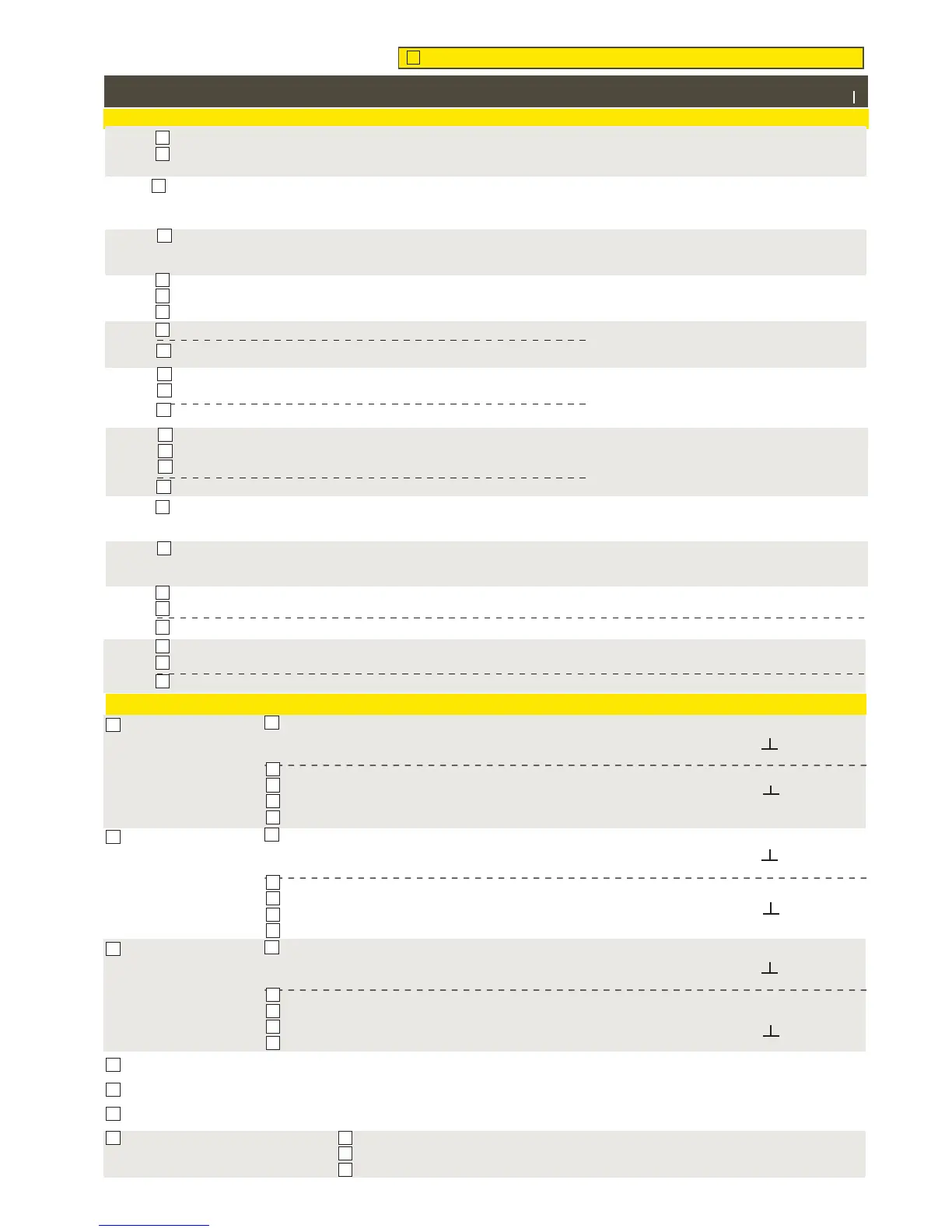
The display shows the pump control mode: on/
o. By pressing OK, you can change the pump
control to manual control. If the manual control
is selected, the hand image appears in the be-
ginning of the line Pump control.
TR2
TR4
TR6
H1 Actuator 24VAC
Voltage control (0-10V)
H2 Actuator 24VAC
Voltage control (0-10V)
DHW Actuator 24VAC
Voltage control (0-10V)
H1 3-point control open
H1 3-point control closed
H2 3-point control open
H2 3-point control closed
P1/S1
P2/S2
P3/S3
DHW 3-point control open
DHW 3-point control closed
3-point
3-point
3-point
Connec-
tion place
Alternative measurement options
Alarm setting values
(factory setting)
Split connectors
M/DI
Input/ Output
Outdoor temperature
Outdoor temperature from bus
H1 Room temperature
H1 Room temp. from bus
DH supply water temp.
H2 Room temp.
H2 Room temp. from bus
DH Return water temp.
Outdoor temperature delay 2.0 h
(setting range 0...6 h)
Manual control option (Inputs and outputs)
Alarm min limit -51°C ( -51°C ... 131 °C)
Alarm max limit 131°C ( -51°C ... 131 °C)
Alarm delay 1 min (0...120)
Alarm min limit -51°C ( -51°C ... 131 °C)
Alarm max limit 131°C ( -51°C ... 131 °C)
Alarm delay 1 min (0...120)
Alarm min limit -51°C ( -51°C ... 131 °C)
Alarm max limit 131°C ( -51°C ... 131 °C)
Alarm delay 1 min (0...120)
Alarm min limit -51°C ( -51°C ... 131 °C)
Alarm max limit 131°C ( -51°C ... 131 °C)
Alarm delay 1 min (0...120)
Alarm min limit -51°C ( -51°C ... 131 °C)
Alarm max limit 131°C ( -51°C ... 131 °C)
Alarm delay 1 min (0...120)
Alarm min limit -51°C ( -51°C ... 131 °C)
Alarm max limit 131°C ( -51°C ... 131 °C)
Alarm delay 1 min (0...120)
Alarm min limit -51°C ( -51°C ... 131 °C)
Alarm max limit 131°C ( -51°C ... 131 °C)
Alarm delay 1 min (0...120)
Alarm min limit -51°C ( -51°C ... 131 °C)
Alarm max limit 131°C ( -51°C ... 131 °C)
Alarm delay 1 min (0...120)
Switch alarm
Alarm delay 1 min (0...120)
Switch alarm
Alarm delay ____1 min (0...120)
11 31
12 32
13 33
14 34
15 35
16 36
17 37
18 38
19 39
27 47
28 48
27 47
28 48
M 1
M 2
M 3
M 4
M 5
M 6
M 7
M 8
M 9
DI 1
DI 2
H1 Supply water
H2 Supply water
DHW Supply water
DHW Circulation water
Alarm Normally open
Alarm Normally closed
Alarm Normally open
Alarm Normally closed
H1 Return water
Free meas. (NTC-10)
Free meas. (NTC-10)
Free meas. (NTC-10)
Return water compensation ratio ____ 2.0
(setting range 0...10)
Return water compensation ratio __2.0
(setting range 0...10)
Room temp. measurement delay 0.5 h
(0...6 h)
Room compensation ratio 2.0 (0...10)
Room temperature delay ____ 0.5 h (0...6 h)
Room compensation ratio___2.0 (0...10)
Name________________________
Name_______________________
Name________________________
Name_________________________
Name________________________
Home/Away switch
Home/Away switch
0...10 V
2...10 V
10...0 V
10...2 V
0...10 V
2...10 V
10...0 V
10...2 V
0...10 V
2...10 V
10...0 V
10...2 V
Alarm min limit -51°C ( -51°C ... 131 °C)
Alarm max limit 131°C ( -51°C ... 131 °C)
Alarm delay 1 min (0...120)
H2 Return water
DHW Supply water (after exchg.)