S-DBS Installation Instructions
Section 300
v1.0
Issue 1 August 1990
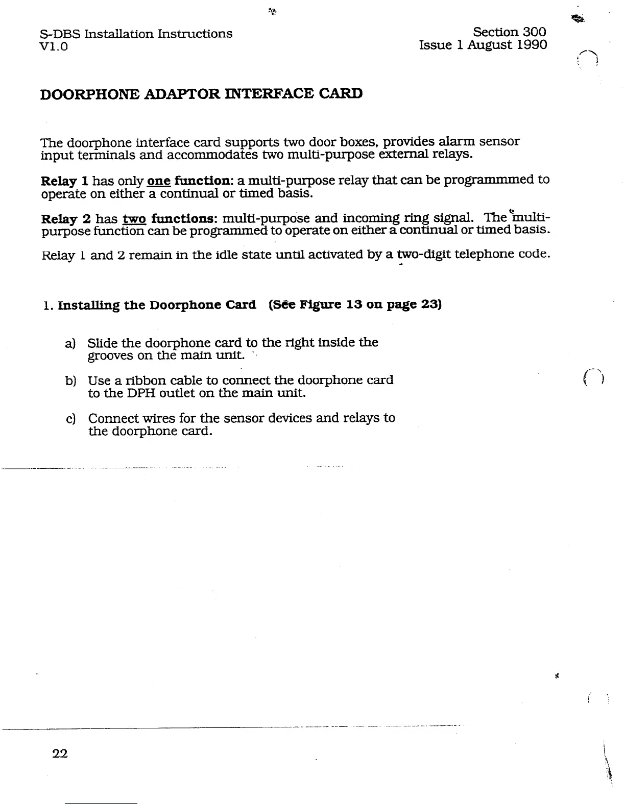
DOORPHONE ADAPTOR INTERFACE CARD
The doorphone interface card supports two door boxes, provides alarm sensor
input terminals and accommodates two multi-purpose external relays.
Relay 1 has only one function: a multi-purpose relay that can be programmmed to
operate on either a continual or timed basis.
Relay 2 has m functions: multi-purpke and incoming ring signal. TheQmulti-
purpose function can be programmed to operate on either a continual or timed basis L
Relay 1 and 2 remain in the idle state until activated by a two-digit telephone code.
d
1. Installing the Doorphone Card
(Se Figure 13 on page 23)
a)
b)
cl
Slide the doorphone card to the right inside the
grooves on the main unit. ‘.
Use a ribbon cable to connect the doorphone card
to the DPH outlet on the main unit.
Connect wires for the sensor devices and relays to
the doorphone card.
____.._.._.__ ..-. .~-. -.-~ ----.--.---- .------.-
22