9.5 Resolution Verification
(1) Leave
the
oscilloscope in
the
same condition
as
mentioned
in
section 9.3.
(2) Resolution
is
calculated
by
the
following
formula
.
• V2Faverage
V
1
Faverage x
lOO
(%)
(3) Check
that
the
calculated value meets
the
specifications
of
Table 8.1.
9.6 Radial
Alignment
Adjustment
Introduction
This adjustment
is
normally
not
necessary.
If
the
mounting
screws
for
the
stepper
motor
loosen,
or
if
parts become defective,
or
if
a
compatibility
error
occurs, check and readjust according
to
the
following
procedure.
Steps (4)
to
(9)
below
should be performed regardless
of
the
type,
CE
or
DAD
alignment
diskette used.
Use
an
alignment
diskette suitable
to
the
type
of
FDD
to
be adjusted according
to
table 3.1.
(1) Insert Panasonic
alignment
diskette.
CAUTION:
Be
sure
to
leave
the
alignment
diskette
under
room conditions
for
20 minutes before adjustment.
(2) Step
to
the
track specified in
the
Radial
alignment
column
of
Table 8.1.
(3) Leave
the
oscilloscope in
the
same condition
as
mentioned
in
section 9.3.
• Cats
Eye
System
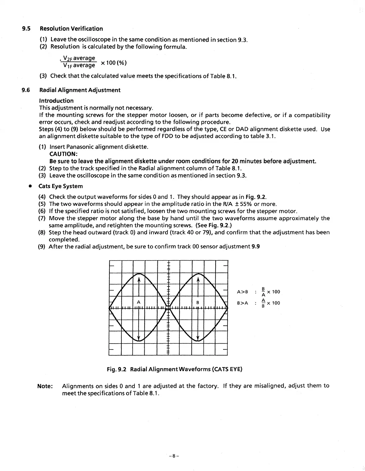
(4) Check
the
output
waveforms
for
sides 0 and
1.
They should appear
as
in Fig. 9.2.
(5) The
two
waveforms should appear in
the
amplitude
ratio
in
the
RIA
± 55%
or
more.
(6)
If
the
specified
ratio
is
not
satisfied, loosen
the
two
mounting
screws
for
the
stepper
motor.
(7) Move
the
stepper
motor
along
the
base
by hand
until
the
two
waveforms assume approximately
the
same amplitude, and retighten
the
mounting
screws.
(See
Fig. 9.2.)
(8) Step
the
head
outward
(track
O)
and
inward
(track
40
or
79), and confirm
that
the
adjustment
has
been
completed.
(9)
After
the
radial adjustment, be sure
to
confirm track 00 sensor adjustment 9.9
A>B
~
x
100
B>A
~
x 100
Fig. 9.2 Radial
Alignment
Waveforms
(CATS
EYE)
Note: Alignments on sides O and 1 are adjusted
at
the
factory.
If
they
are misaligned, adjust
them
to
meet
the
specifications
of
Table 8.1.
-B-
 Loading...