12.9 Removing and Remounting
the
Eject Lever
Springs
(1) Remove
the
holder assembly according
to
the
procedure in section 12.4.
(2) Remove
the
hook
of
the
eject lever spring and
remove the eject lever spring.
(3) Remount
the
eject lever spring in
the
reverse
procedure
of
steps (1) and (2).
Fig. 12-9. Removing
the
Eject Lever Spring
12.10 Removing and Remounting
the
Eject Lever
(1) Remove the eject lever springs according
to
the
procedure
in
section 12.9.
(2)
Remove
the
trigger
lever assembly according
to
the
procedure in section 12.8.
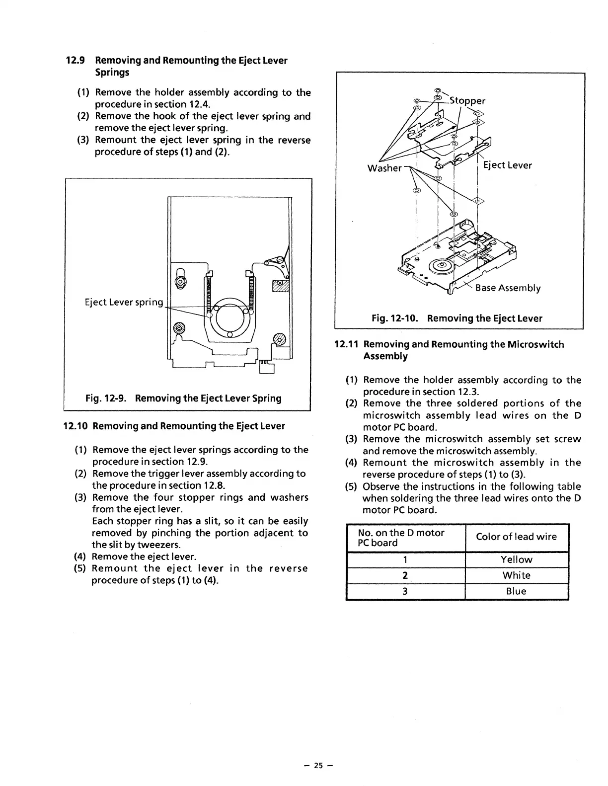
(3) Remove
the
four
stopper
rings and washers
from
the
eject lever.
Each
stopper ring
has
a slit,
so
it
can
be easily
removed by pinching
the
portion
adjacent
to
the
slit by tweezers.
(4) Remove
the
eject lever.
(5)
Remount
the
eject
lever
in
the
reverse
procedure
of
steps (1)
to
(4).
- 25 -
Fig. 12-10. Removing
the
Eject Lever
12.11 Removing and Remounting
the
Microswitch
Assembly
(1) Remove
the
holder assembly according
to
the
procedure
in
section 12.3.
(2)
Remove
the
three
soldered
portions
of
the
microswitch
assembly
lead
wires
on
the
D
motor
PC
board.
(3) Remove
the
microswitch
assembly set screw
and remove
the
microswitch assembly.
(4)
Remount
the
microswitch
assembly
in
the
reverse procedure
of
steps
(1)
to
(3).
(5) Observe
the
instructions in
the
following
table
when
soldering
the
three lead wires
onto
the
D
motor
PC
board.
No.
on
the
D
motor
Color
of
lead
wire
PC
board
1
Yellow
2
White
3
Blue