(2) Move the shutter lever assembly in
the
arrow
direction in
the
figure riding
across
the
stopper
until
it
reaches
the
dotted line position, remove
the shutter lever assembly
with
the tab
on the
holder aligned
with
the hole, and remove the
shutter lever spring from
the
holder.
(3) Remove the reverse insertion preventive lever
spring from the tab.
(4) Move
the
reverse insertion preventive lever
until
it
reaches
the
doted
line position and
remove
it
with
the
tab
on the holder aligned
with
the hole.
(5)
Reassemble
the holder assembly in
the
reverse
procedure
of
steps (1)
to
(4).
The reverse insertion
preventive lever spring
Shutter Lever
Assembly
Set
the
lever
down
the
rib
of
holder
¢===:!
Shutter Lever
Spring
Holder
Fig. 12-17. Disassembling
the
Holder Assembly
- 28 -
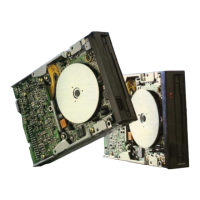
12.18 Mounting the Drive
Motor
LED
(1) Solder
the
LED
in
the
position
indicated
in
figure 12-18.
Drive
Motor
LED
Fig. 12-18. Mounting the Drive
Motor
LED
 Loading...