• DAD (Dynamic
Alignment
Diskette)
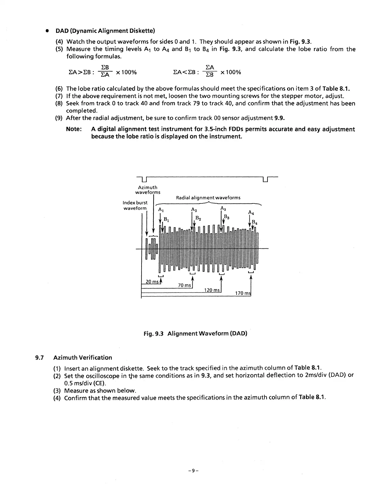
(4) Watch
the
output
waveforms
for
sides 0 and
1.
They should appear
as
shown in Fig. 9.3.
(5) Measure
the
timing
levels A
1
to
A
4
and B
1
to
B
4
in Fig. 9.3, and calculate
the
lobe
ratio
from
the
following
formulas.
:EB
:EA
:EA>:EB:
:EA
x 100%
:EA<:EB:
EB
x 100%
(6) The lobe
ratio
calculated by
the
above formulas should meet
the
specifications on
item
3
of
Table 8.1.
(7)
If
the
above requirement
is
not
met, loosen
the
two
mounting
screws
for
the
stepper
motor,
adjust.
(8)
Seek
from
track 0
to
track
40
and from track
79
to
track 40, and confirm
that
the
adjustment
has
been
completed.
(9)
After
the
radial adjustment, be sure
to
confirm track
00
sensor adjustment 9.9.
Note: A
digital
alignment
test
instrument
for
3.5-inch
FDDs
permits accurate and easy
adjustment
because
the
lobe
ratio
is
displayed on
the
instrument.
Azimuth
waveforms
Index burst
Radial
alignment
waveforms
Fig. 9.3
Alignment
Waveform (DAD)
9.7
Azimuth
Verification
(1) Insert an
alignment
diskette.
Seek
to
the
track specified in
the
azimuth column
of
Table 8.1.
(2) Set
the
oscilloscope in t)le same conditions
as
in 9.3, and set horizontal
deflection
to
2ms/div (DAD)
or
0.5 ms/div
(CE).
(3) Measure
as
shown below.
(4) Confirm
that
the
measured value meets
the
specifications in
the
azimuth
column
of
Table 8.1.
-9-
 Loading...