(10)After
remounting
the
above, adjust
the
radial
alignment
according
to
the
procedure
in
section 9.6, adjust
the
track
00
sensor according
to
the
procedure in section 9.9.
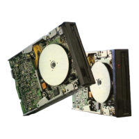
Head carriage assembly
Fig.12-6.
The mounting position
of
the guide rod
Guide rod L
The position
projected from
the
baselessthan 1 mm.
Removing
the
Head Carriage
Assembly,
Rod
Clamp, and Guide
Rod
12.7 Removing and Remounting
the
Track 0
Assembly
(1) Remove
the
cover according
to
the
procedure
in section 12.1.
(2) Remove
the
track 0 cable connector according
to
the
procedure in section 12.5.
(3) Remove
the
set screw on
the
track 0 assembly
and remove
the
track 0 assembly.
(4) Remount
the
track 0 assembly in
the
reverse
procedure
of
steps (1)
to
(3).
(5)
After
remounting
track 0 assembly, adjust
the
track
00
sensor according
to
the
procedure in
9.9.
;
~
I [ i Track 0 Assembly
I ' I
I I j
I
..
.
11
Fig. 12-7. Removing Track 0 Assembly
-
17
-
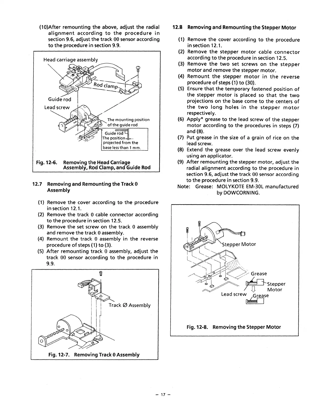
12.8 Removing and Remounting
the
Stepper
Motor
(1) Remove
the
cover according
to
the
procedure
in section 12.1.
(2) Remove
the
stepper
motor
cable
connector
according
to
the
procedure in section 12.5.
(3) Remove
the
two
set screws
on
the
stepper
motor
and remove
the
stepper
motor.
(4)
Remount
the
stepper
motor
in
the
reverse
procedure
of
steps (1)
to
{30).
(5) Ensure
that
the
temporary fastened position
of
the
stepper
motor
is
placed
so
that
the
two
projections on
the
base
come
to
the
centers
of
the
two
long
holes
in
the
stepper
motor
respectively.
(6)
Apply*
grease
to
the
lead screw
of
the
stepper
motor
according
to
the
procedures in steps (7)
and (8).
(7) Put grease
in
the
size
of
a grain
of
rice on
the
lead screw.
(8) Extend
the
grease over
the
lead screw evenly
using an applicator.
(9)
After
remounting
the
stepper
motor,
adjust
the
radial
alignment
according
to
the
procedure in
section 9.6, adjust
the
track
00
sensor according
to
the
procedure in section 9.9.
Note: Grease: MOL
YKOTE
EM-30L manufactured
by DOWCORNING.
Stepper
Motor
Fig. 12-8. Removing
the
Stepper
Motor
 Loading...