(4) Remount
the
above in
the
reverse procedure
of
steps (
1)
to
(3).
In this
case,
be sure
to
insert
the
head
FPC
to
the
full
extent
in
the
right
angle.
Wiring
should be made
so
that
the
lead
wire
of
the
track 0 and
the
stepper
motor
does
not
contact
the
carriage
of
the
head
or
hang over
the
track
0.
(5)
Ensure
that
the
head
FPC
is
not
higher
than
the
track O assembly.
(6)
Ensure
that
the
head
FPC
does
not
contact
the
head
of
the
track 0 assembly set screw.
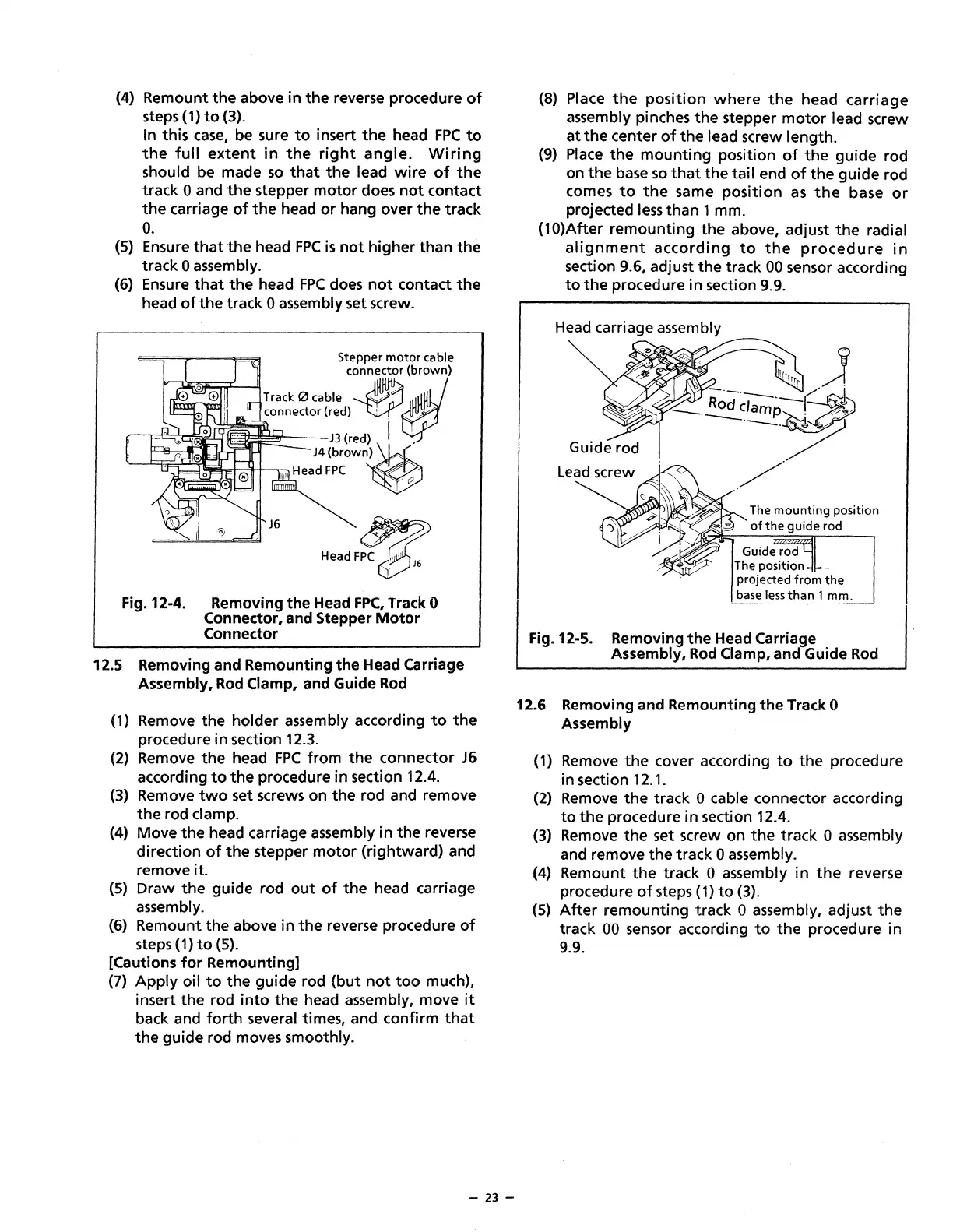
Fig.12-4.
""df~
Removing the Head
FPC,
Track 0
Connector, and Stepper
Motor
Connector
12.5 Removing and Remounting
the
Head Carriage
Assembly,
Rod
Clamp, and Guide
Rod
(1)
Remove the holder assembly according
to
the
procedure in section 12.3.
(2)
Remove
the
head
FPC
from
the
connector
J6
according
to
the
procedure in section 12.4.
(3)
Remove
two
set screws on
the
rod and remove
the
rod clamp.
(4)
Move
the
head carriage assembly in
the
reverse
direction
of
the
stepper
motor
(rightward) and
remove it.
(5)
Draw
the
guide rod
out
of
the
head carriage
assembly.
(6) Remount
the
above
in
the
reverse procedure
of
steps
(1)
to
(5).
[Cautions
for
Remounting]
(7)
Apply
oil
to
the
guide rod
(but
not
too
much),
insert
the
rod
into
the
head assembly, move
it
back and
forth
several times, and confirm
that
the
guide rod moves smoothly.
- 23 -
(8)
Place
the
position
where
the
head
carriage
assembly pinches
the
stepper
motor
lead screw
at
the
center
of
the
lead screw length.
(9)
Place
the
mounting
position
of
the
guide rod
on
the
base
so
that
the
tail end
of
the
guide rod
comes
to
the
same
position
as
the
base
or
projected
less
than
1 mm.
(10)After remounting
the
above, adjust
the
radial
alignment
according
to
the
procedure
in
section 9.6, adjust
the
track
00
sensor according
to
the
procedure in section 9.9.
Head
carriage assembly
Fig.12-5.
J
R·-·----~·
I
-~<~~·····/~
/"
The
mounting
position
of
the
guide rod
Guide rod L
The position -
projected
from
the
base
less
than
1 mm.
Removing
the
Head Carriage
Assembly,
Rod
Clamp, and Guide
Rod
12.6 Removing and Remounting
the
Track 0
Assembly
(1)
Remove
the
cover according
to
the
procedure
in section 12.1.
(2) Remove
the
track 0 cable connector according
to
the
procedure in section 12.4.
(3) Remove
the
set screw on
the
track 0 assembly
and remove
the
track 0 assembly.
(4)
Remount
the
track 0 assembly
in
the
reverse
procedure
of
steps (1)
to
(3).
(5)
After
remounting track 0 assembly, adjust
the
track
00
sensor according
to
the
procedure in
9.9.
 Loading...