12.15 Removing and Remounting
the
Control
PC
Board
(1) Remove
the
mounting bracket according
to
the·
procedure in section 12.14.
(2) Remove
the
head
FPC,
track0
connector, and
stepper
motor
connector
according
to
the
procedure in section 12.5.
(3) Remove
the
three set screws
from
the
control
PC
board.
(4) Remove
the
D
motor
PC
board socket housing
from
the
connector
JS
and remove
the
control
PC
board.
(S)
Remount
the
control
PC
board
in
the
reverse
procedure
of
steps (1)
to
(4 ).
(6) Treat
the
cable
in
the
D
motor
PC
board socket
housing
as
shown in
figure
12-15.
Fig.12-15. Removing
the
Control
PC
Board
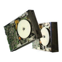
12.16 Removing and Remounting
the
Drive
Motor
Assembly
(1) Remove
the
holder assembly according
to
the
procedure in section 12.4.
(2) Remove
the
control
PC
board according
to
the
procedure in section 12.15.
(3) Remove
the
microswitch assembly according
to
the
procedure in section 12.13.
(4) Remove
the
three
front
(head side) drive
motor
set screws.
(S)
Remove
the
three back
(PC
board side)
drive
motor
set screws and remove
the
drive
motor
assembly.
Drive
Motor
Assembly
Fig.12-16. Removing
the
Drive
Motor
Assembly
12.17 Disassembling and Reassembling
the
Mounting
Bracket Assembly
(1)
Press
the
collar
bracket
from
beneath
the
mounting
bracket
assembly
with
a
minus
screwdriver,
then
the
collar bracket and washer
are removed
from
the
holes in the
mounting
bracket.
(2)
Reassemble
the
mounting bracket assembly in
the
reverse order
of
step (1).
- 20 -
 Loading...