48
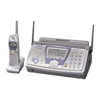
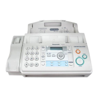
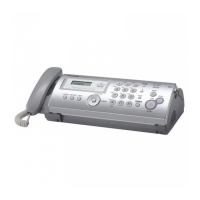
KX-FP365CX / KX-FM388CX
6.8. ITS (Integrated telephone System) and Monitor Section
6.8.1. General
The general ITS operation is performed by the special IC5 which has a handset circuit. The alarm tone, the key tone, and the beep
are output from the ASIC IC1 (digital board). During the pulse dial operation, the monitor tone is output from the ASIC IC1.
6.8.2. Speakerphone Circuit
1. Function
The circuit controls the automatic switching of the transmitted and received signals, to and from the telephone line, when the
unit is used in the hands-free mode.
2. Circuit Operation
The speakerphone can only provide duplex.
3. Signal path
Refer to Check Sheet for Signal Route (P.125).
6.8.3. Handset Circuit
1. Function
This circuit controls the conversation over the handset, i.e. the transmitted and received voices to and from the handset.
2. Signal path
Refer to Check Sheet for Signal Route (P.125).
6.8.4. Monitor Circuit for Each Signals
1. Function
This circuit monitors various tones, such as 1 DTMF tone, 2 Alarm/Beep/Key tone/Bell.
2. Signal path
Refer to Check Sheet for Signal Route (P.125).
6.9. ATAS (Automatic Telephone Answering System) Section
1. Function
The ATAS main operation is performed by the special IC5 (MODEM). IC8 (FLASH MEMORY) control signals are input from
ASIC IC1.
a. Greeting/Message Recording
b. ICM Recording
c. Greeting/Message/ICM play to speaker
d. Greeting/Message/ICM play to Tel Line
e. Vox Detection
2. Signal Path
Refer to Check Sheet for Signal Route (P.125).
 Loading...
