Chapter 2 Getting Started — Connecting
60 - ENGLISH
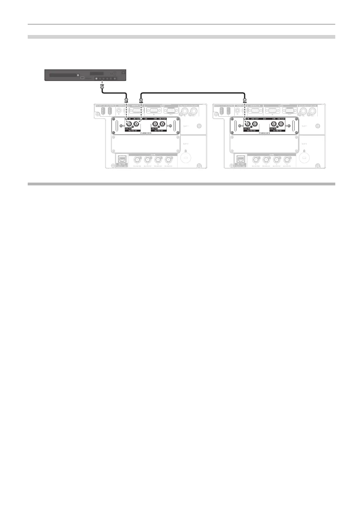
For <SDI 1 IN>/<SDI 2 IN/1 OUT>/<SDI 3 IN>/<SDI 4 IN/3 OUT> terminals of the Interface Board
This is an example when the optional Interface Board for 12G-SDI (Model No.: ET-MDN12G10) is installed in
<SLOT 1>.
SD-SDI signal, HD-SDI signal, 3G-SDI signal, 6G-SDI signal, or 12G-SDI signal
12G-SDI signal output compatible device
Note
f Use a connection cable of 5C-FB or higher (such as 5C-FB, or 7C-FB), Belden 1694A or higher, or L-5.5CUHD manufactured by Canare
Electric Co., Ltd. to properly transmit images. The maximum cable length that can be used is as follows. However, this maximum cable
length is a rough guideline, and does not guarantee the transmission distance.
g SD-SDI signal, HD-SDI signal, 3G-SDI signal: 150 m (492'2")
g 6G-SDI signal: 80 m (262'6") (When L-5.5CUHD is used, the cable length should be 110 m (360'11").)
g For 12G-SDI signal, the cable length will differ depending on the setting in the [DISPLAY OPTION] menu → [SLOT IN] → [SDI MODE].
When [SDI MODE] is set to [INPUT]: 50 m (164'1") (When L-5.5CUHD is used, the cable length should be 100 m (328'1").)
When [SDI MODE] is set to [OUTPUT]: 50 m (164'1") (When L-5.5CUHD is used, the cable length should be 90 m (295'3").)
f When the [DISPLAY OPTION] menu → [SLOT IN] → [SDI MODE] is set to [OUTPUT], attach a terminating resistor (75 Ω) to the terminal
with no device connected as an output destination.
f Use the BNC connector that is compatible with the coaxial cable and type of the signal to be used.
f Setting the [DISPLAY OPTION] menu → [SLOT IN] is required depending on the connected external device or the input signal.
f Setting the [DISPLAY OPTION] menu → [SLOT IN] → [SDI LINK] is required when the dual link signal or the quad link signal is input.
f To input the dual link signal, use the cable with same length and same type for connecting to the <SDI 1 IN> terminal and the <SDI 3 IN>
terminal. The image may not be projected correctly when the difference of the cable length is 4 m (13'1") or more.
f To input the quad link signal, use the cable with same length and same type for connecting to each of <SDI 1 IN>/<SDI 2 IN/1 OUT>/<SDI 3
IN>/<SDI 4 IN/3 OUT> terminals. The image may not be projected correctly when the difference of the cable length is 4 m (13'1") or more.
f Directly connect the projector with the external device that will output the signal without going through a distributor, etc., when inputting dual
link signals. A phase difference is generated between the Link A signal and the Link B signal, and the image may not be projected correctly.
f Directly connect the projector with the external device that will output the signal without going through a distributor, etc., when inputting quad
link signals. A phase difference is generated between the signals of Link 1, Link 2, Link 3, and Link 4, and the image may not be projected
correctly.
f An error in signal detection may occur when an unsteady signal is input to the projector. In such case, set the [DISPLAY OPTION] menu →
[SLOT IN] to the content corresponding to the input signal.
f The <SDI 2 IN/1 OUT> terminal and the <SDI 4 IN/3 OUT> terminal do not support the input of the 6G-SDI signal or the 12G-SDI signal.
f To use the <SDI 2 IN/1 OUT> terminal or the <SDI 4 IN/3 OUT> terminal as an output terminal, set the [DISPLAY OPTION] menu → [SLOT
IN] → [SDI MODE] to [OUTPUT].
f Install this board in either <SLOT 1> or <SLOT 2>. When these boards are installed in both <SLOT 1> and <SLOT 2>, only the board
installed in <SLOT 1> can be used.
 Loading...