14
3-1. Preparation for Suspending
This unit uses a drain pump. Use a carpenter’s level to check that the unit is level.
3-2. Suspending the Indoor Unit
3. HOW TO INSTALL THE INDOOR UNIT
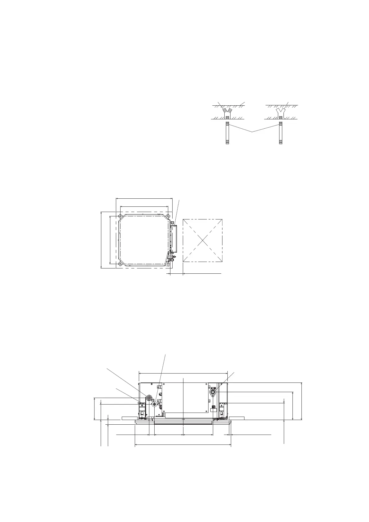
(3) Determine the pitch of the suspension bolts using the supplied full-scale installation diagram
(printed on container box).
The diagram show the relationship between the positions of the suspension fitting, unit, and
panel.
Use the nut (field supply) and washer (supplied) for upper and lower position of the
suspension lug.
Hole-in-anchor
Hole-in-plug
Concrete
Insert
Suspension bolt
(M10 or 3/8”)
(field supply)
(1) Fix the suspension bolts securely in the
ceiling using the method shown in the
diagrams, by attaching them to the ceiling
support structure, or by any other method
that ensures that the unit will be securely
and safely suspended.
(2) Follow the diagram to make the holes in the ceiling.
Install the inspection opening on the electrical component box side where maintenance and
inspection of the electrical component box and drain pump are easy.
* The overlapping portion between the ceiling and panel for cassette should be kept over 20 mm.
Refrigerant tubing joint (liquid side)
Drain outlet (other side)
(VP20)
Refrigerant tubing joint (gas side)
* Over 20 mm
34 mm 186 mm
625 mm
575 mm
193 mm
144 mm
103 mm
112 mm
184 mm
243 mm
30 mm
Suspension lug
Indoor Unit
View from top
B: 585 ~ 600 mm
A: (suspension bolt pitch)
B: (ceiling opening dimension)
Electrical component box
Over 100 mm
Inspection access
450 mm × 450 mm
(Field supply)
A: 530 mm
B: 585 ~ 600 mm
A: 530 mm
01_330918_EU_Eng.indb 14 2021/9/9 11:26:43
 Loading...