43
●
Be sure to attach the safety strap that prevents the air intake grille from dropping off to the
panel for cassette unit as shown in the figure.
Hole of panel for cassette hook
Hook that prevents the grille from
dropping
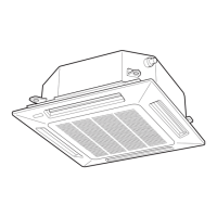
●
With this panel for cassette, the directions of the air intake grille lattices when installing
multiple units, and the position of the label showing the company name on the corner panel,
can be changed according to customer’s requests, as shown in the figure. However, the
wireless signal receiver can only be installed at the refrigerant-tubing corner of the ceiling
unit.
Can be installed rotated 90°
Refrigerant tube side
Locations of air intake grille hinges at shipment
* The grille can be installed with these hinges facing in
any of 4 directions.
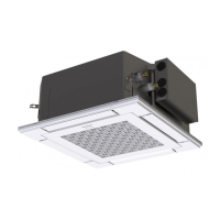
Electrical component box
Optional wireless receiver kit
* This position is only possible for
installation.
Corner cover installation position
marked with the Panasonic Logo
at shipment.
* Installation possible at any of 4
corners
Drain pipe side
7-3. Others
(1) Checking After Installation
1) Check that there are no gaps between the unit and the panel for cassette, or between the
panel for cassette and the ceiling surface.
* Gaps may cause water leakage and condensation.
2) Check that the wiring is securely connected.
* If it is not securely connected, the auto flap will not operate.
(“P09” is displayed on the remote controller.)
In addition, the water leakage and condensation may occur.
(2) Operating the Wireless Remote Controller
For details of installation, refer to the Installation Instructions attached to the optional
Wireless Remote Controller.
(3) Setting the Flap Separately
1) The 4-air outlet flap can be adjusted separately
during operation. When not adjusted separately, all
flaps operate in the same manner.
Air outlet flap
(adjustment for up-down airflow direction)
01_330918_EU_Eng.indb 43 2021/9/9 11:26:54
 Loading...