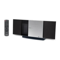
Do you have a question about the Panasonic SC-HC37GN and is the answer not in the manual?
| Type | Micro System |
|---|---|
| Output Power | 20 W |
| Speaker System | 2.0 |
| Bluetooth | Yes |
| CD Player | Yes |
| FM Radio | Yes |
| AM Radio | Yes |
| USB Port | Yes |
| Wall Mountable | Yes |
| NFC | Yes |
| iPod/iPhone Dock | No |
| Weight (main unit) | 2.5 kg |
| Total Output Power | 40W (RMS) |
Basic procedures for safe servicing, including lead dressing and protective devices.
Procedure for checking leakage current with the unit unplugged.
Procedure for checking leakage current with the unit connected to AC power.
Important warnings and instructions for handling the AC cord and fuse replacement.
Precautions for discharging capacitors and performing repairs safely.
Explanation of the protection circuitry and troubleshooting steps.
Guidelines for safely replacing fuses, including type and manufacturer.
List of critical safety components and their specifications for replacement.
Techniques to prevent damage to sensitive electronic components from static electricity.
Safety precautions when working with the laser diode, avoiding hazardous radiation exposure.
Information on lead-free solder usage and precautions for repair work.
Careful handling procedures for the optical pickup unit and grounding for ESD prevention.
Overview of the service manual's content and ordering parts.
Instructions on how to insert and remove media like CDs, iPods, and USB devices.
Guide to operating playback functions for CD, iPod/iPhone, and USB media.
Detailed explanation of button functions on the main unit and remote control.
Diagrams and instructions for connecting antennas and power.
Procedures to enter and exit the self-diagnostic mode for system checks.
Tables listing error codes for CD mechanism, power amp, iPod, and sliding door operations.
Procedures and tables for accessing the doctor mode for various checks and settings.
Details on FL display tests, volume settings, and sliding panel reliability checks.
Information on CD traverse tests, EEPROM checksum, and cold start procedures.
Tests for region setting, CD LSI version, DSP firmware, and model settings.
Flowchart describing the process for checking the mecha sliding panel reliability.
Flowchart for testing the CD traverse unit's track access and play functions.
Flowchart for testing CD open/close, access, and traverse operations.
Table mapping region numbers to models, series, and countries for tuner settings.
Table detailing model settings with iPod and shock proof functions.
Explanation of the basic operation of the electric sliding door.
Details on how to operate the electric panel using keys on the unit or remote control.
Visual flowchart illustrating the sequence for disassembling the unit's casing and internal parts.
Identification of different types of screws used in the unit for service.
Diagram showing the location of major internal components and PCBs within the unit.
Step-by-step instructions for removing the base stand assembly.
Detailed steps for disassembling and assembling the door mechanism.
Instructions for disassembling and assembling the left and right front ornament units.
Step-by-step guide for removing the front panel assembly.
Detailed instructions for disassembling and assembling the iPod dock block.
Procedure for safely removing the interlock switch printed circuit board.
Steps for disassembling the remote sensor printed circuit board.
Instructions for disassembling and assembling the gear box mechanism.
Procedure for removing the motor printed circuit board.
Steps for disassembling the belt and pulley gear components.
Instructions for safely removing the motor assembly.
Procedure for disassembling the centering spring and stopper mechanisms.
Steps for disassembling lever spring, trigger lever, and driver gear A.
Procedure for disassembling the SW lever, relay gear, and driver gear B.
Instructions for disassembling the shutter mechanism and its spring.
Steps for removing the upper guide rail and top ornament parts.
Procedure for disassembling the bottom ornament component.
Instructions for disassembling the lower guide rail.
Step-by-step guide for disassembling the SMPS (Switched-Mode Power Supply) PCB.
Procedure for safely replacing the diode D1700, including heatsink precautions.
Instructions for disassembling the panel PCB and button ornament unit.
Detailed steps for removing the button printed circuit board.
Instructions for disassembling the button ornament component.
Step-by-step guide for disassembling the CD playback mechanism.
Detailed procedures for disassembling the CD servo printed circuit board.
Instructions for disassembling the jack lid assembly.
Step-by-step guide for disassembling the main printed circuit board.
Instructions for disassembling the passive radiator units SP3 and SP4.
Steps for disassembling the front speaker unit SP1.
Instructions for disassembling the front speaker unit SP2.
Steps for disassembling the passive radiator unit SP5.
Instructions for disassembling the passive radiator unit SP6.
Detailed steps for checking and repairing the SMPS PCB.
Procedure for checking and repairing the panel PCB.
Steps for checking and repairing the CD servo PCB.
Procedure for checking and repairing the main PCB, side B.
Procedure for checking and repairing the main PCB, side A.
Block diagram showing the servo and system control functions (part 1).
Block diagram illustrating the servo and system control functions (part 2).
Table detailing the terminal functions of key integrated circuits.
Block diagram illustrating the audio signal path and processing.
Block diagram of the power supply system (part 1).
Block diagram of the power supply system (part 2).
Important notes and symbols used in the schematic diagrams.
Schematic diagram for the CD servo circuit (part 1).
Schematic diagram for the CD servo circuit (part 2).
Schematic diagram of the main circuit (part 1).
Schematic diagram of the main circuit (part 2).
Schematic diagram of the main circuit (part 3).
Schematic diagram of the main circuit (part 4).
Schematic diagram for the iPod and remote sensor circuitry.
Schematic diagram for panel, interlock switch, motor, and button circuits.
Schematic diagram for the Switched-Mode Power Supply (SMPS) circuit.
Layout of the CD Servo Printed Circuit Board, showing component placement.
Layout of the Main Printed Circuit Board (Side A).
Layout of the Main Printed Circuit Board (Side B).
Layouts of the iPod and Remote Sensor Printed Circuit Boards.
Layouts of the Panel, Interlock Switch, and Motor PCBs.
Layouts of the Button and SMPS Printed Circuit Boards.
Standard voltage values and waveform examples for troubleshooting.
Voltage measurement table for CD Servo PCB (part 1).
Voltage measurement table for CD Servo PCB (part 2).
Voltage measurement table for Main PCB (part 1).
Voltage measurement table for Main PCB (part 2).
Voltage measurement table for Main PCB (part 3).
Voltage measurement table for Panel PCB.
Voltage measurement table for SMPS PCB.
Visual examples of waveforms for key signal points.
Illustrations and part numbers for common ICs, transistors, and diodes.
Detailed terminal functions for the Micro Processor IC (IC6002).
Exploded views and lists of mechanical parts for assembly and replacement.
Diagram showing the location of cabinet parts in an exploded view.
Diagram illustrating the packaging contents and layout of the product.
Comprehensive list of mechanical replacement parts with safety references and quantities.
List of electrical components, including PCBs, ICs, transistors, and diodes, with part numbers.