Do you have a question about the Panasonic TH-50PC77U and is the answer not in the manual?
Lists mechanical replacement parts, including part numbers and names.
Covers power, display panel, sound, channel capability, and operating conditions.
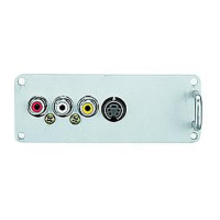
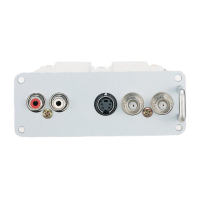
Lists and describes various input and output connection ports on the TV.
Covers 3D Y/C filter, Closed Caption, V-Chip, Photo Viewer, and HDAVI Control 2.
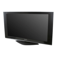
Provides physical dimensions of the TV with the pedestal attached.
Provides physical dimensions of the TV without the pedestal.
Specifies the weight of the TV with the pedestal attached.
Specifies the weight of the TV without the pedestal.
Provides general recommendations to follow during servicing for safety.
Details the procedure for checking leakage current when the unit is unplugged.
Details the procedure for checking leakage current when the unit is powered on.
Highlights critical components that must be replaced with manufacturer-specified parts.
Recommends specific types of lead-free solder for use in repairs.
Instructions and diagram for removing the rear cover of the TV.
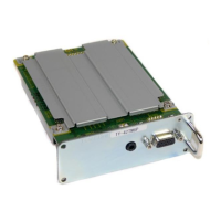
Lists main circuit boards (P, A, K, S, etc.) and their primary functions.
Steps for removing the rear cover, terminal cover, and P-Board.
Procedures for removing tuner, side AV, G/GS, D, and SU boards.
Instructions for removing SD, SC, SS2, and SS3 boards.
Steps for removing C1, C2, C3 boards, speakers, and the plasma panel.
Procedures for removing K/S boards and reassembling the TV with the new panel.
General cautions regarding cable assembly and connector locking.
Illustrates the routing of specific internal wiring connections.
Shows the routing and securing of internal wiring, including clamps and AC inlet.
Details wiring paths for connectors P2, P11, P12, D25, and SC-Board.
Illustrates wiring routes for cables P6-A6, D5-A5, and P7-A7.
Explains how to access and interpret the IIC bus line check function.
Details LED blink patterns and troubleshooting for no power faults.
Troubleshooting for no picture and analysis of local screen failures.
Explains the procedure to enter and use the service menu and its key commands.
Details adjustable parameters, SOS history, power count, and service tool access.
Procedure for adjusting driver section voltages and parameters using a multimeter.
Procedure for adjusting stand-down pulse (T2) period using an oscilloscope.
Steps for PCB replacement and post-exchange voltage adjustments.
Diagrams showing the location of adjustment potentiometers and test points.
Detailed procedure for adjusting white balance using a color analyzer.
Explains the purpose of hotel mode and the button sequence to enter the setup menu.
Describes the various settings and options available within the hotel mode menu.
High-level overview of the TV's main functional blocks and interconnections.
Detailed block diagram illustrating the functions of the P-Board.
Series of diagrams showing the internal block structure of the A-Board.
Block diagrams illustrating the functionality of SC, SU, and SD boards.
Detailed circuit schematics for the P-Board, split into two parts.
Comprehensive circuit schematics for the A-Board, presented in multiple parts.
Circuit schematics for the C1, C2, and C3 boards, detailing their internal connections.
Detailed circuit schematics for the D-Board, provided in multiple parts.
Visual representation of the TV's internal components with numerical references.
Diagram showing the layout of items included in the accessories box.
Explains abbreviations and important safety notices for parts identification.
Comprehensive list of mechanical replacement parts for the PDP TV model.
List of replacement parts specifically for the TV stand.
Specifies that parts marked [PAVCA] are sourced from PAVCA, others from PAVC-CSG.
| Screen Size | 50 inches |
|---|---|
| Display Type | Plasma |
| Resolution | 1366 x 768 |
| Aspect Ratio | 16:9 |
| Contrast Ratio | 10000:1 |
| HDMI Inputs | 2 |
| Component Video Inputs | 2 |
| Composite Video Inputs | 1 |
| S-Video Inputs | 1 |
| PC Input | 1 |
| Audio Output | 2 x 10W |