30
TH-65PF12EK
9.22.3. Removal of Cabinet Assy
1. Remove the Front Glass.
(Refer to Removal of Front Glass)
2. Remove V1-Board and V2-Board.
(Refer to Removal of V1-Board and V2-Board)
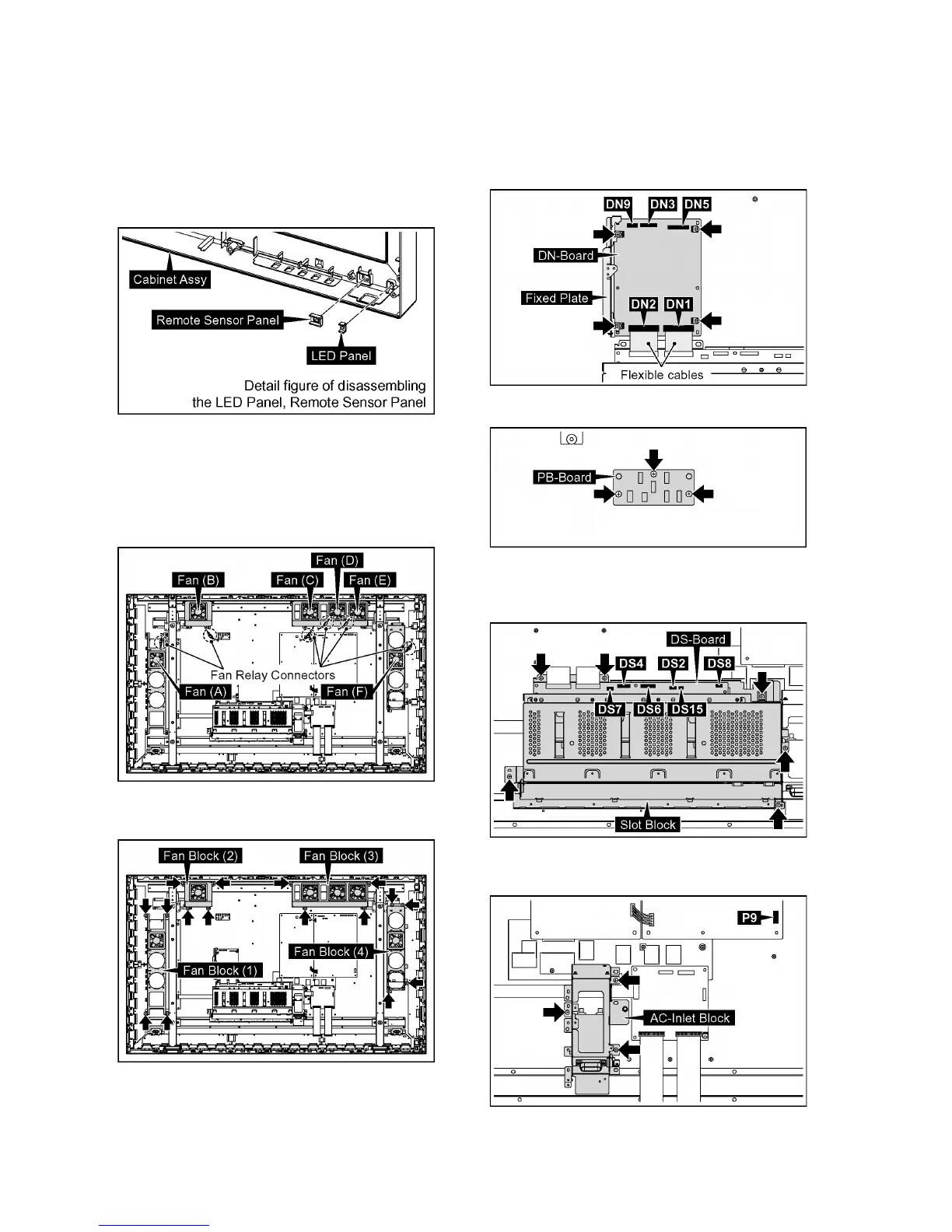
3. Remove the LED Panel and Remote Sensor Panel.
4. Exchange the Cabinet Assy.
9.23. Removal of Plasma Display
Panel
The C1, C2, C3 Boards are connected with the Plasma Dis-
play Panel for the repair.
1. Disconnect the Fan Relay Connectors.
2. Remove 16 screws and then remove the Fan Blocks (1,
2, 3, 4).
3. Disconnect the connectors (DN3, DN5, DN9).
4. Remove the flexible cables from the connectors (DN1,
DN2).
5. Remove 4 screws and then remove the DN-Board and
Fixed Plate.
6. Remove 3 screws and then remove PB-Board.
7. Disconnect the connectors (DS2, DS4, DS6, DS7, DS8,
DS15).
8. Remove 6 screws and then remove the Slot Block.
9. Disconnect the connector (P9).
10. Remove 3 screws and then remove the AC-Inlet Block.
 Loading...