25
Connection
Caution:
• FORULLISTEDMODEL(S),ONLYCONNECT12VDCCLASS2POWERSUPPLY.
Before starting the connection, turn off the power of this camera and the devices to be connected.
Before start the connection, prepare the required devices and cables.
z Connect the RCA pin cable to the monitor
output connector for adjustment on the
rear (only for adjustment of the angle field
of view).
IMPORTANT:
• The monitor output connector is providedonlyforcheckingtheadjustmenttheanglefieldof
view on the video monitor when installing the camera or when servicing. It is not provided for
recording/ monitoring use.
• Blackbandsmayappearatthetop,bottom,rightandleftofthescreen.(Thereisnoproblem
with adjustment since the angle field of view is not affected.)
• Thevideooutputonthemonitorforadjustmentdoesnotguaranteethevideoperformanceor
image quality.
x Connect the microphone to MIC/LINE IN (for use of the audio reception function).
Input impedance: Approx. 2 kΩ
Recommended cable length: 1 m {3.3 feet} or less (for microphone input)
10 m {33 feet} or less (for LINE input)
Recommended microphone: Plug-in power type microphone (option)
Connect a monaural mini plug (ø3.5 mm).
• Supplyvoltage:2.5V±0.5V
• Recommendedsensitivityofmicrophone:–48dB±3dB(0dB=1V/Pa,1kHz)
IMPORTANT:
• Connect/disconnecttheaudiocablesandturnonthepowerofthecameraafterturningoffthe
power of the audio output devices. Otherwise, loud noise may be heard from the speaker.
c Connect an external speaker with amplifier to the audio output connector (for use of the audio
transmission function).
Connect a stereo mini plug (ø3.5 mm) (Audio output is monaural.).
• Recommendedcablelength:10m{33 feet} or less
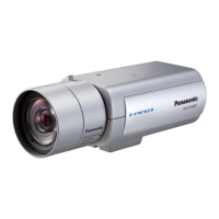
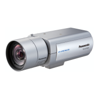
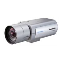
(This illustration represents WV-SP509.)
POWER
10BASE T/100BASE-TX
AUDIO OUT MIC/LINE IN
EXT I/O
SD CARD/ABF
MONITOR OUT
ACT LINK
12V = IN
GND 4 3 2 1
INITIAL
SET
ALARM IN 1/DAY/NIGHT IN
ALARM IN 3/AUX OUT ALARM IN 2/ALARM OUT
Connect to
the video
monitor, etc.
 Loading...