26
v Connect external devices to the EXT I/O terminal.
When connecting an external device, remove 9 mm - 10 mm
{11/32 inches - 13/32 inches} of the outer jacket of the cable
and twist the cable core to prevent the short circuit first.
Specification of cable (wire): 22 AWG - 28 AWG
Single core, twisted
• Checkwhetherthestrippedpartofthewireisnotexposedandissecurelyconnected.
4 3 2 1
r GND
e AUX OUT
w ALARM OUT
q ALARM IN
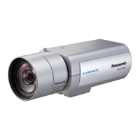
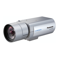
<WV-SP508>
IMPORTANT:
• Donotconnect2wiresormoredirectlytoaterminal.Whenitisnecessarytoconnect 2or more
wires, use a splitter.
• InputandoutputoftheEXTI/Oterminal2and3canbeswitchedbyconfiguringthesetting."Off"is
selected by default. It is possible to determine whether or not to receive input from EXT I/O terminal 2
and 3 (ALARM IN2, 3) by selecting "Off", "Alarm input", "Alarm output" or "AUX output" for "Terminal
2"or"Terminal3"onthe[Alarm]tabonthe"Alarm"page.RefertotheOperatingInstructions(includ-
ed in the CD-ROM) for further information.
• WhenusingtheEXTI/Oterminalsastheoutputterminals,ensuretheydonotcausesignalcollision
with external signals.
• Connectanexternaldevicewithverifyingthattheratingsarewithinthespecificationsabove.
• WhenusingtheEXTI/Oterminalsastheoutputterminals,ensuretheydonotcausesignalcollision
with external signals.
<Ratings>
• ALARMOUT,AUXOUT
Output specification: Open collector output (maximum applied voltage: 20 V DC)
Open: 4 V - 5 V DC by internal pull-up
Close: Output voltage 1 V DC or less (50 mA or less)
• ALARMIN/DAY/NIGHTIN*
Input specification: No-voltage make contact input (4 V - 5 V DC, internally pulled up)
OFF: Open or 4 V - 5 V DC
ON: Make contact with GND (required drive current: 1 mA or more)
* DAY/NIGHT IN is only for WV-SP509.
b Connect a LAN cable (category 5 or better,
STP*) to the network connector on the rear of
the camera.
* E models only
 Loading...