8 Chapter 2: Overview
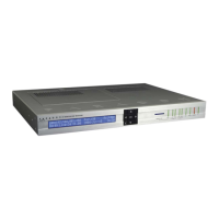
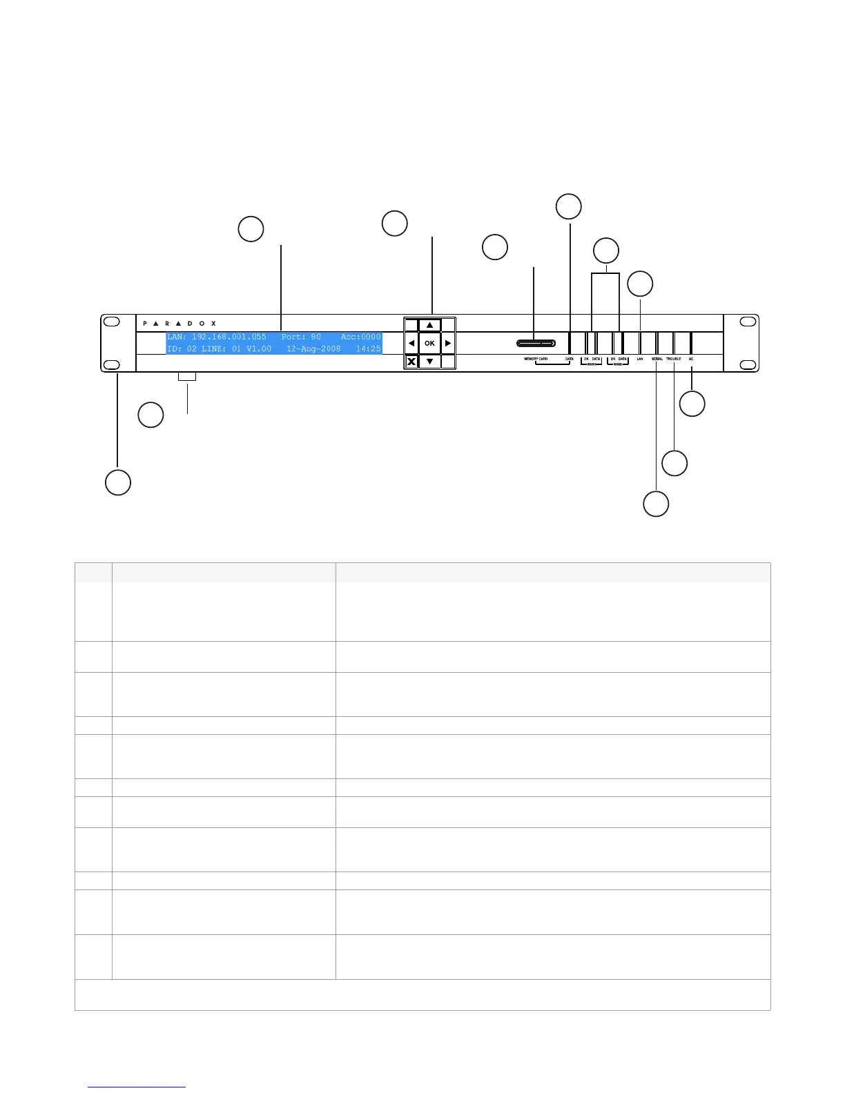
IPR512 Receiver Overview - Front View
The following provides a description of the IPR512 Receiver system components located in the
front of the unit.
Figure 3: IPR512 Receiver Front View
Table 4: IPR512 Receiver Front View Components
# Item Description
1 LCD Display A 40-character Liquid Crystal Display (LCD) screen used to display
IPR512 Receiver status and modify system settings. For more
information, refer to “Chapter 6: IPR512 Receiver LCD System
Configuration” on page 42.
2 Control Keypad Used to navigate the status display screen and setting menus of the
IPR512 Receiver.
3 Memory Card Slot Used to store backup data and system configuration information for the
IPR512 Receiver. For more information, refer to “Installing the Memory
Card for Data Backup” on page 14.
4 Data Status LED On when memory card is accessed.
5 WAN1 and WAN2 Status LEDs OK LED - On when WAN1 or WAN2 interface is connected to a
network.
DATA LED - On when sending or receiving data.
6 LAN Status LED On when LAN interface is connected to a network.
7 Serial Port Status LED On when IPR512 Receiver is communicating with the automation
software (ACK/NACK).
8 Trouble Status LED On when IPR512 Receiver is experiencing problems. For more
information on the Trouble Status LED, refer to “Chapter 7:
Troubleshooting and Maintenance” on page 44.
9 AC Power Status LED On when AC power is present.
10 Rack-Mounting Bracket Optional mounting hardware used to install the IPR512 Receiver on a
standard 19” (48.3 cm) rack. For more information, refer to “Rack-
Mount” on page 10.
11 Desktop Mounting Feet Optional mounting hardware used to install the IPR512 Receiver on a
desk or similar type surface. For more information, refer to “Desk-
Mount” on page 11.
For more information on the IPR512 Receiver Status LEDs, refer to “Chapter 7: Troubleshooting and
Maintenance” on page 44.
IP Monitoring Receiver
IPR512
LCD
Display
1
Control
Keypad
Memory
Card Slot
3
Data
Status LED
4
WAN 1 & 2
Status LEDs
5
6
Serial Port
Status LED
Trouble
Status LED
AC Power
Status LED
LAN
Status LED
7
8
9
Rack-Mounting
Bracket
Desktop
Mounting Feet
10
11
2
IP Monitoring Receiver
IPR512
LCD
Display
1
Control
Keypad
Memory
Card Slot
3
Data
Status LED
4
WAN 1 & 2
Status LEDs
5
6
Serial Port
Status LED
Trouble
Status LED
AC Power
Status LED
LAN
Status LED
7
8
9
Rack-Mounting
Bracket
Desktop
Mounting Feet
10
11
2