Chapter 2: Overview
9
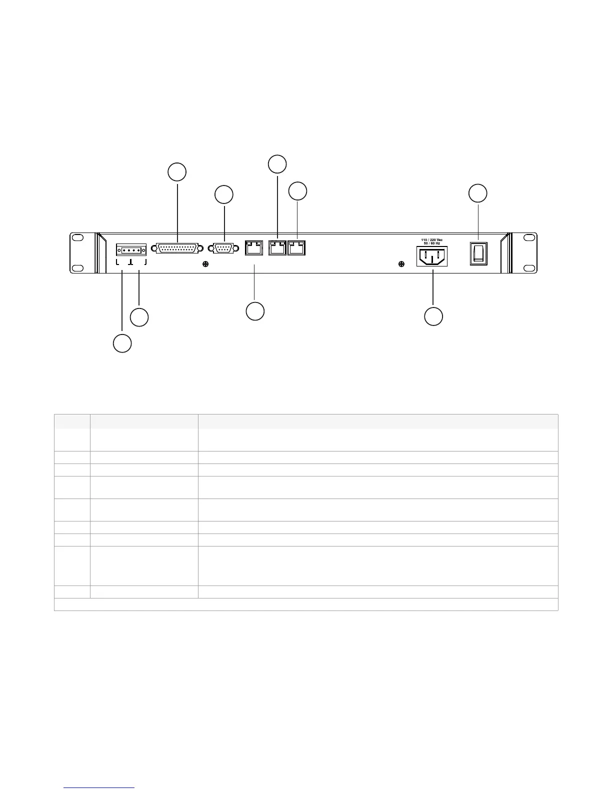
IPR512 Receiver Overview - Back View
The following provides a description of the IPR512 Receiver system components located in the
back of the unit.
Figure 4: IPR512 Receiver Back View
Table 5: IPR512 Receiver Back View Components
# Item Description
1 Input Trigger Dry contact relay used to generate an event that can be reported to the
automation software.
2 Output Relay Dry contact relay used to activate an external device.
3 COM1 Port Serial port used to connect the IRP512 to a PC running the automation software.
4 COM2 Port Serial port used to send events to serial printer or to a PC running a RS-232 serial
communication program.
5 LAN LAN port used to connect to a LAN or directly to a PC for configuration of the
IPR512 Receiver.
6 WAN1 Ethernet port used to receive events through an Internet Service Provider (ISP).
7 WAN2 Ethernet port used to receive events through an Internet Service Provider (ISP).
8 AC Input Provides AC power to the IPR512 Receiver.
Note: Compatible with multiple types of outlets. Contact your local distributor for more
information.
9 Power Switch Powers up the IPR512 Receiver.
For more information on IPR512 Receiver connections, refer to “Chapter 4: Connection” on page 12.
COM 1
(PC)
COM
2
(SERIAL OUT)
LAN WAN
1 WAN 2
INPUT
TRIGGER
C1
COM NO
OUTPUT
RELAY
I
O
PARADOX.COM
Input
Trigger
1
Output
Relay
2
COM1
Port
3
COM2
Port
4
LAN
5
WAN1
6
WAN2
7
AC Input
8
Power Switch
9