58 Programming Guide
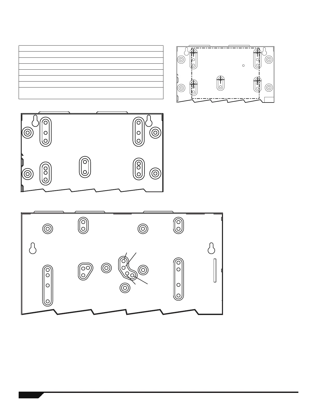
Metal Box Installation
Use the numbered holes in the following diagram to identify the correct mounting location for the control panel being installed. If you
require specific dimensions, contact Paradox Distributor Support.
Identify the correct mounting holes according to the following table:
8x10”Metal Box
11x11” Metal Box
Product 8x10” Metal Box Holes 11x11” Metal Box Holes
MG5000* 3, 6, 9, 11, 14 6, 8, 12, 18, 20
MG5050 11x11” box only 1, 4, 11, 19, 22
SP4000 5, 7, 13, 16 7, 19, 20
SP5500 1, 2, 17, 18 1, 2, 11, 19, 21
SP6000 1, 2, 17, 18 1, 2, 11, 19, 21
SP7000 11x11” box only 1, 4, 11, 19, 22
* For UL recommended installation for the MG5000 only, place the
PCB one notch lower than the mounting location.
Example: Install an MG5000 in an 8x10” box as follows:
3
4
5
9
10
11
12
13
6
7
8
14
15
16
2
1
18
17
1
2
3
4
5
20
21
22
23
6
7
18
1916
17
89
10
12 13
14 15
11
 Loading...