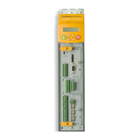
E-12 Technical Specifications
DC590+ DRV Series DC Digital Drive
Terminal Information - Power (Frames 1-5)
Note: On Frame 1 and 2 units, L1, L2, L3, A+ and A- terminals are located on a separate Terminal Board. On Frame 3, 4 & 5 units, they are
busbar connections.
Terminal Terminal Function Signal Level Customer Terminals
Description Frames 1, 2 Frames 3, 4, 5
Field Output
F-
DC supply for motor field connections.
The DC output voltage at these terminals will depend upon the AC supply voltage and the
mode of field control.
Voltage Control
The output voltage will be determined by the ratio parameter in the field variables. The
relationship between the dc output voltage and AC input voltage is determined by the
equation:-
Vdc
Vratio x VAC
100
=
The default value of Vratio is 90% hence the DC output voltage will be the same as for a
full wave diode rectifier, i.e., 90% is maximum output.
0.9 x Vac F- F-
Field Output
F+
DC supply for motor field connections. 0.9 x Vac F+ F+
Auxiliary supply
Aux N
Neutral 115V
50-60Hz line-to-line
CONTROL
N
L7
Auxiliary supply
Aux L
Line
These terminals are the mains input connections for the switch mode power supply and
contactor control relay supply.
115V
50-60Hz line-to-line
L L6
Do not connect
external control
power if using the
control
transformer
option

 Loading...


