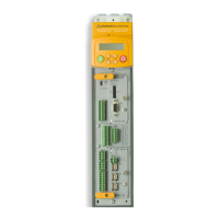
E-18 Technical Specifications
DC590+ DRV Series DC Digital Drive
Terminal Information – Control Board
This Control Board is common to all 590 units.
Terminal Description Terminal Function Signal Level Configurable Terminal
Number
Program Stop Input
Program Stop
When the Program Stop input is held at +24V, the
drive operates as required by the inputs. When the
Program Stop is open circuit or at zero volts, the
controller provides a controlled or program stop as
defined by the Program Stop parameters.
+24V drive run
0V (o/c) drive program stop
Threshold +16V
NO B8
Coast Stop Input
Coast Stop
When the Coast Stop input is at +24V, the controller
operates normally. When the Coast Stop is at zero
volts or open circuit, the main contactor is open and
the drive no longer operates. The motor coasts to
rest.
+24V drive run
0V (o/c) drive coasts to rest.
Threshold +16V
NO B9
TERMINAL BLOCK C
0V (Signal)
Zero Volt Reference 0V N/A C1
External Trip Input
An external interlock or permissive.
External permissive element should be connected to
C1 to run.
If not using this feature, connect a jumper between
C1 and C2.
May be used as an unisolated motor thermal input
NO C2
Start/Run Input
Start/Run
When an input is applied to this terminal, the main
contactor will close and the controller will operate
provided there are no alarms, program stop/coast
stop signals are high and the controller is enabled.
When the input is removed the controller will perform
a regenerative stop to zero speed. A regenerative
stop can only be achieved by a 4 quad regenerative
controller; the 2 quad non-regenerative controller
will coast to zero speed.
+24V = True/Run
0V (o/c) = False/Normal Stop
Threshold + 16V
NO C3

 Loading...


