E-20 Technical Specifications
DC590+ DRV Series DC Digital Drive
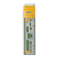
Terminal Information – Control Board
This Control Board is common to all 590 units.
Terminal Description Terminal Function Signal Level Configurable Terminal
Number
Digital Input 3
Current Demand Isolate
This input alters the drive operation from Speed
Control to Current Control. When digital input No. 3
is true, analog input No. 2 provides the current
demand and the speed loop is disconnected. When
false the speed loop is in control and analog input
No. 2 is an auxiliary speed setpoint.
Access encoder mode set-up & output parameters via
the ENCODER 2 function block.
+24V = True/Current
0V = False/Speed
Threshold + 16V
Encoder CLK/DIRECTION Mode: DIRECTION INPUT
+5V to +24V, or 0V
YES C8
+24V Supply
+24V Maximum output current: 200mA
Note that the maximum combined consumption for
digital outputs 1, 2 & 3 and C9 should not exceed
300mA.
Some typical loads are given below:
Microtach : 75mA
Relays : 50mA each
Fiber Optic ancillaries : 50mA each
DeviceNetTechnology Box : 50mA
N/A C9

 Loading...


