Technical Data
54 192-120102 N7 - February 2004
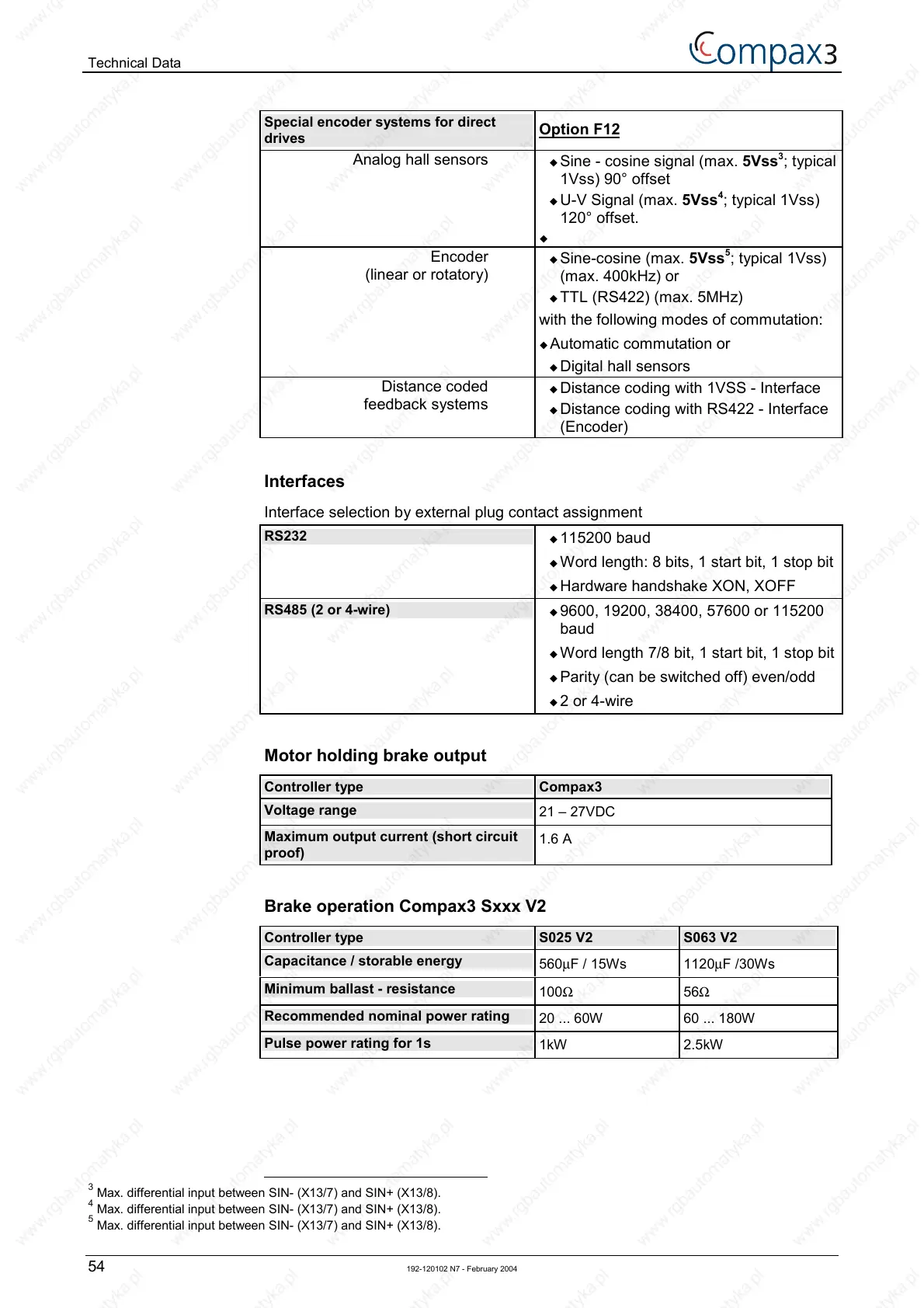
Special encoder systems for direct
drives
Option F12
Analog hall sensors
! Sine - cosine signal (max. 5Vss
3
; typical
1Vss) 90° offset
! U-V Signal (max. 5Vss
4
; typical 1Vss)
120° offset.
!
Encoder
(linear or rotatory)
! Sine-cosine (max. 5Vss
5
; typical 1Vss)
(max. 400kHz) or
! TTL (RS422) (max. 5MHz)
with the following modes of commutation:
! Automatic commutation or
! Digital hall sensors
Distance coded
feedback systems
! Distance coding with 1VSS - Interface
! Distance coding with RS422 - Interface
(Encoder)
Interfaces
Interface selection by external plug contact assignment
RS232
! 115200 baud
! Word length: 8 bits, 1 start bit, 1 stop bit
! Hardware handshake XON, XOFF
RS485 (2 or 4-wire)
! 9600, 19200, 38400, 57600 or 115200
baud
! Word length 7/8 bit, 1 start bit, 1 stop bit
! Parity (can be switched off) even/odd
! 2 or 4-wire
Motor holding brake output
Controller type Compax3
Voltage range
21 – 27VDC
Maximum output current (short circuit
proof)
1.6 A
Brake operation Compax3 Sxxx V2
Controller type S025 V2 S063 V2
Capacitance / storable energy
560µF / 15Ws 1120µF /30Ws
Minimum ballast - resistance
100Ω 56Ω
Recommended nominal power rating
20 ... 60W 60 ... 180W
Pulse power rating for 1s
1kW 2.5kW
3
Max. differential input between SIN- (X13/7) and SIN+ (X13/8).
4
Max. differential input between SIN- (X13/7) and SIN+ (X13/8).
5
Max. differential input between SIN- (X13/7) and SIN+ (X13/8).

 Loading...


