Compax3 device description
26 192-120102 N7 - February 2004
3.2.9. Analog / Encoder (plug X11)
PIN X11 Reference
High Density Sub D
1 +24V (output for encoder) max. 70mA
2
Ain1 -: analogue input - (14-bit)
3 D/A monitor channel 1 (±10V, 8-bit resolution)
4 D/A monitor channel 0 (±10V, 8-bit resolution)
5 +5V (output for encoder) max. 150mA
6
- Input: steps RS422 (5V - level)
A/ (encoder input/emulation)
7
+ Input: steps RS422 (5V - level)
A (encoder input/emulation)
8 + Input: direction RS422 (5V - level)
B (encoder input/emulation)
9 Ain0 +: analogue input + (14-bit)
10 Ain1 +: analogue input + (14-bit)
11
Ain0 -: analogue input - (14-bit)
12
- Input: direction RS422 (5V - level)
B/ (encoder input/emulation)
13 Reserved
N/ (Encoder simulation)
14 Reserved
N (Encoder simulation)
15 GND
The exact assignment depends on the the device type!
You will find the description of the device-specific assignment in the online help
which can be opened from the Compax3 – ServoManager.
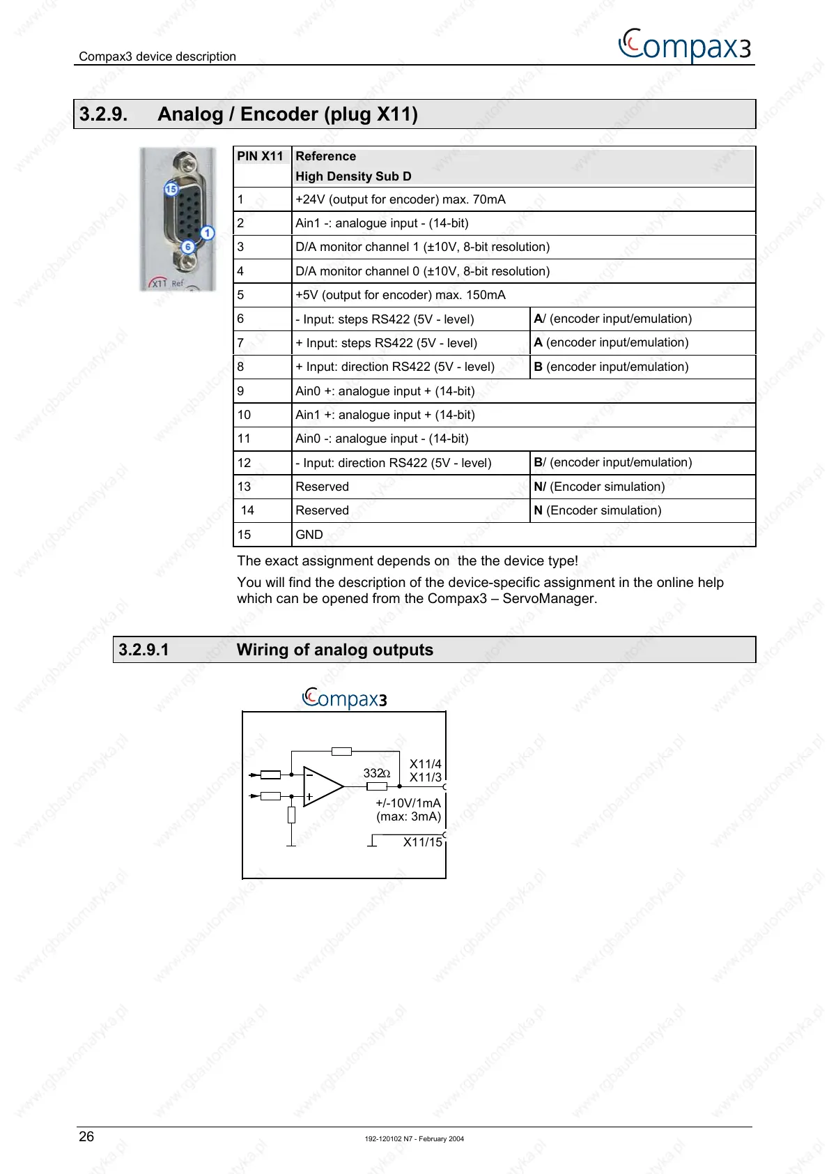
3.2.9.1 Wiring of analog outputs
+/-10V/1mA
(max: 3mA)
X11/3
X11/15
332Ω
X11/4

 Loading...


