Parker EME
Compax3 device description
192-120102 N7 - February 2004 27
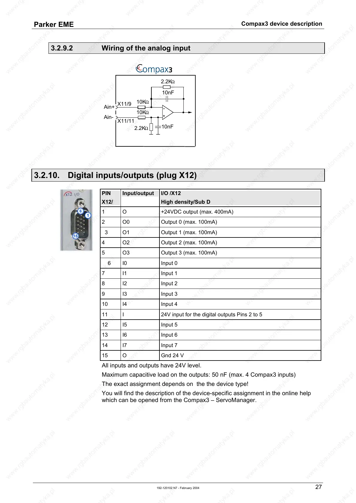
3.2.9.2 Wiring of the analog input
10nF
2.2K
Ω
10K
Ω
Ain+
2.2K
Ω
X11/9
10K
Ω
10nF
Ain-
X11/11
3.2.10. Digital inputs/outputs (plug X12)
PIN
X12/
Input/output I/O /X12
High density/Sub D
1 O +24VDC output (max. 400mA)
2 O0 Output 0 (max. 100mA)
3 O1 Output 1 (max. 100mA)
4 O2 Output 2 (max. 100mA)
5
O3 Output 3 (max. 100mA)
6 I0 Input 0
7 I1 Input 1
8 I2 Input 2
9 I3 Input 3
10
I4 Input 4
11 I 24V input for the digital outputs Pins 2 to 5
12 I5 Input 5
13 I6 Input 6
14
I7 Input 7
15
O Gnd 24 V
All inputs and outputs have 24V level.
Maximum capacitive load on the outputs: 50 nF (max. 4 Compax3 inputs)
The exact assignment depends on the the device type!
You will find the description of the device-specific assignment in the online help
which can be opened from the Compax3 – ServoManager.

 Loading...


