Serial Ethernet Recovery Flexcan (SERF) Development Board
Note: a daughter board with a matrix style keypad or encoder can be connected to
J1 through J12.
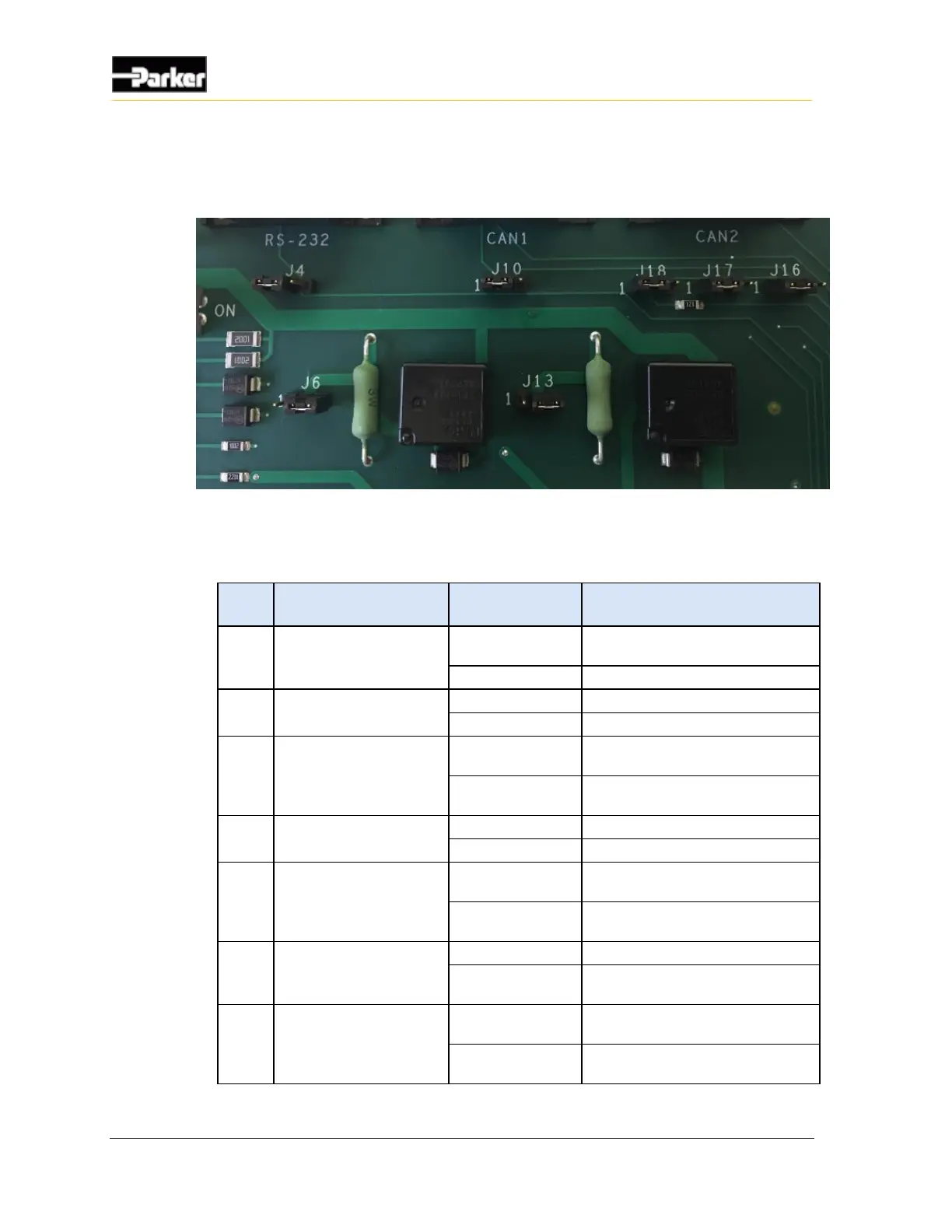
Figure 17: Power and communication jumpers
The following table describes the corresponding jumpers associated with power
and communication.
Enable RS232 Input from RS232
Connector.
Intended for factory use.
For 12Vdc (nom.) power supply.
For 24Vdc (nom.) power supply.
Disconnect internal termination
resistor to CAN 1.
Connect internal termination resistor
to CAN 1.
For 12Vdc (nom.) power supply.
For 24Vdc (nom.) power supply.
Connects CAN 1 high to CAN 2
high.
Disconnects CAN 1 high to CAN 2
high.
Connects CAN 1 low to CAN 2 low.
Disconnects CAN 1 low to CAN 2
low.
Disconnect external termination
resistor to CAN 2.
Connect internal termination resistor
to CAN 2.

 Loading...


