SmartNode 200 overview 18
SmartNode 200 User Manual 2 • General information
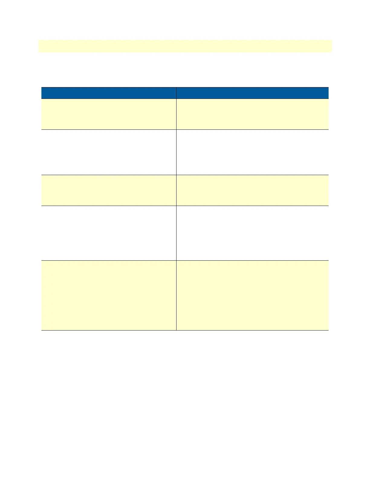
SN200 rear panel ports and LEDs are described in table 1.
Table 1. Rear panel ports and LED Definitions
Port/LED Description
Ethernet port
ETH 0/0
(The SN200/1JS1V/EUI Ethernet port is not
labeled)
RJ-45 connector that connects the SmartNode device to
an Ethernet device (e.g., a cable or DSL modem, or LAN
switch).
Analog voice ports,
FXS 0/0–0/3
FXO 0/1
FXS RJ-11 (6 position, 4 wire) connectors that connect
the SmartNode device with an analog terminal (a tele
-
phone, for example)
FXO RJ-11 (6 position, 4 wire) connectors that connect
POTS lines as per (ETSI EG201 188).
Power port The SmartNode device requires 12 VDC, 1.25 A power
for operation. Every SmartNode device comes with an
external power supply converting from AC to DC power
(100–240 VAC, 50/60 Hz).
Ethernet port line speed LED
• When lit, the SN200 is operating at 100 Mbps
• Off indicates the SN200 is operating at 10 Mbps
Note The SN200/1JS1V/EUI Ethernet port
has no LED on the connector, it is
located on the side - described in the
front panel LED description.
Ethernet port activity LED
• When lit, indicates the Ethernet connection has a link
indication.
• Flashes when data is received or transmitted at the
Ethernet port.
Note The SN200/1JS1V/EUI Ethernet port
has no LED on the connector, it is
located on the side - described in the
front panel LED description.