Introduction 49
SmartNode 200 User Manual D • Port pin-outs
Introduction
This section provides pin-out information for the ports of the SmartNode.
Ethernet
Note Pins not listed are not used.
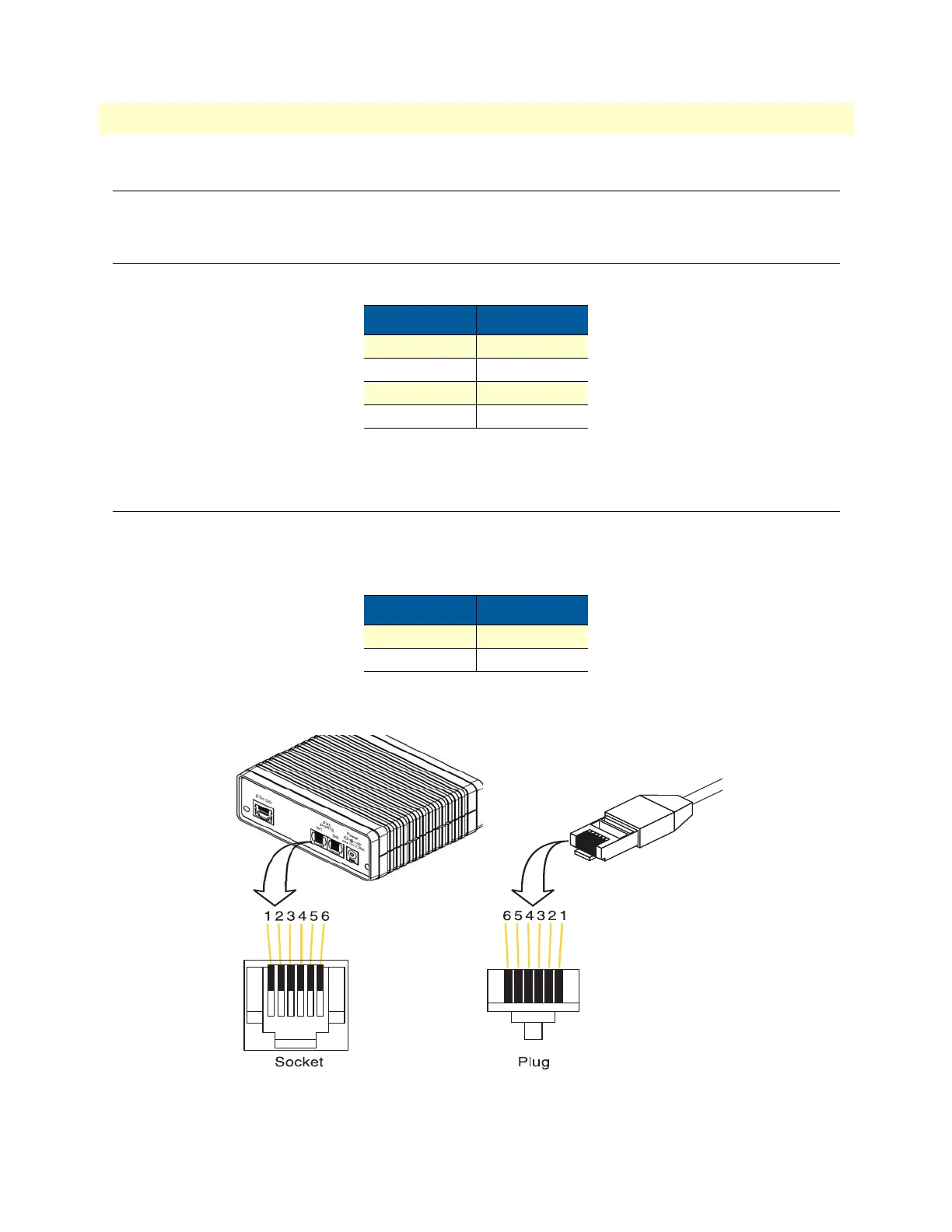
FXS port
The FXS ports use an RJ-11 connector with 6 positions. The middle two positions 3 and 4 are used according
to
table 7 and figure 14.
Note Pins not listed are not used.
Figure 14. RJ-11 pinout diagram
Table 6. 10/100 Base-T RJ-45 socket
Pin Signal
1 TX+
2 TX-
3 RX+
6 RX-
Table 7. RJ-11 socket
Pin Signal
3 Ring (-)
4 Tip (+)