Installing the SmartNode device 28
SmartNode 200 User Manual 4 • SmartNode Installation
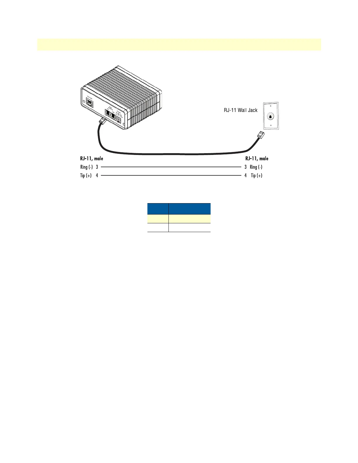
Figure 8. Analog FXO connection
Connecting the 10/100Base-T Ethernet LAN cable
The SmartNode device has automatic MDX (auto-cross-over) detection and configuration on the Ethernet
port.
1. Connect the straight-through wired LAN cable to port ETH 0/0.
2. Connect the other end of the LAN cable to a host or switch.
For details on the Ethernet port pinout and cables, refer to Appendix C, “Cabling” on page 44 and Appendix
D, “Port pin-outs” on page 48.
Connecting the power supply
Do the following to connect main power to the SmartNode device:
1. Verify that the AC power supply included with your device is compatible with local standards. If it is not,
refer to Chapter
6, “Contacting Patton for Assistance” on page 35 to find out how to replace it with a com-
patible power supply.
Note The SmartNode does not have a power switch; it powers on when the device
is plugged in.
2. The power connection is made via the barrel jack on the rear panel of the SmartNode. No configuration is
necessary for the power supply. Connect the female end (barrel plug) to the barrel jack on the rear of the
SmartNode (see
figure 2 on page 17).
3. Connect the power supply male connector to an appropriate power outlet.
Table 4. RJ-11 socket
Pin Signal
3 Ring (-)
4 Tip (+)