Installing the SmartNode device 27
SmartNode 200 User Manual 4 • SmartNode Installation
Connecting cables
Connect the cables in the following order:
1. Connect the RJ-11 FXS analog port cable or cables (see page 27)
2. If your device is equipped with an FXO port, connect the RJ-11 FXO analog port cable
3. Connect the 10/100Base-T Ethernet LAN cable (see page 28)
Connecting analog interface cable or cables
SN200 models are available with FXS or with 1 FXS and 1 FXO ports.
Check the product webpage under the ordering tab for a detailed list of available models.
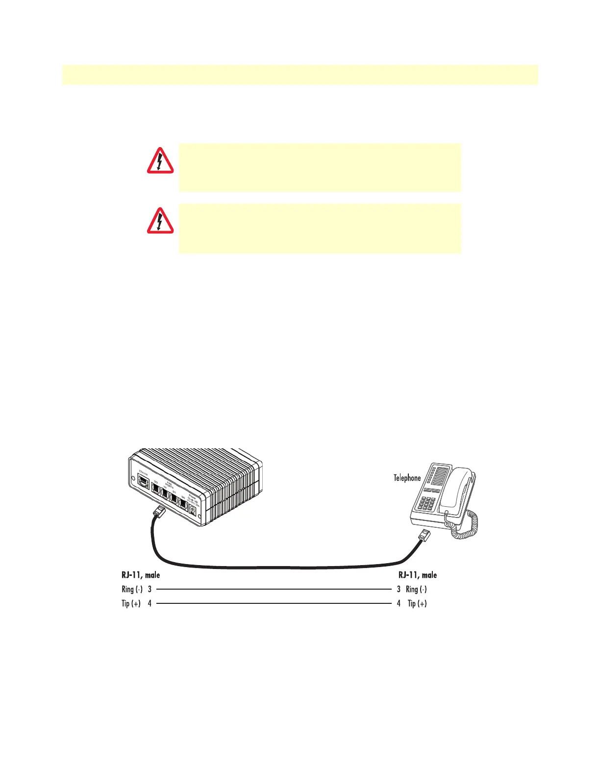
The FXS interfaces are connected to analog devices via cables (see figure 7) terminated with RJ-11 connectors
(see section “Analog FXS” on page 46), while the same type of cable and pinout is being used to connect a
POTS line to the FXO ports of the SmartNode (see figure 8 on page 28).
Figure 7. Analog FXS connection
Do not work on the system or connect or disconnect
cables during periods of lightning activity.
The interconnecting cables shall be acceptable for external
use and shall be rated for the proper application with
respect to voltage, current, anticipated temperature, flam
-
mability, and mechanical serviceability.