460906 Rev. D 8/2020 MASTERTEMP
125 Pool and Spa Heater Installation and User’s Guide
35
Section 1. Installation Instructions
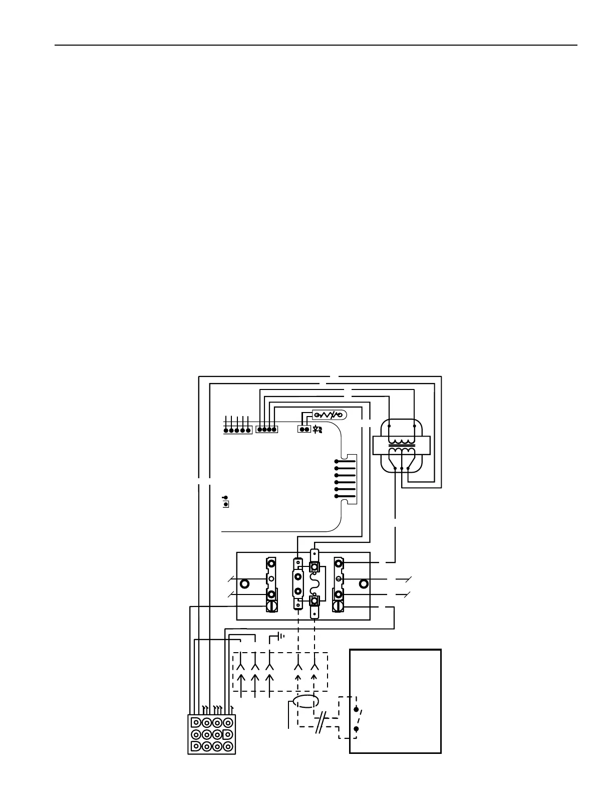
USE THE PROVIDED WATERPROOF WIRE NUTS WHEN CONNECTING THE POWER SUPPLY.
A time clock controlling the lter pump should have a low-voltage Fireman’s Switch that switches off the heater at
least 15 minutes before shutting off the pump.
1. - Remove the factory installed jumper from the Fireman’s Switch terminals.
- Connect wires between the Fireman’s Switch terminals on the heater and the relay. Connect wires from the
controller or timer to the Fireman’s Switch. Controller, timer or relay should be sized to handle 24VAC at 0.5
Amp (because it will be completing the 24VAC control board circuit on the heater as shown in Figure 31 and
Figure 37 (page 40). DO NOT apply line voltage to the Fireman’s Switch terminals. Use 18 gauge wire with a
minimum 1.2 mm (3/64 in.) thick insulation rated for a temperature rise of at least 105° C.
- Knock-outs are provided to route the wires through the bottom of the control box and past the junction box.
2. Toconnecta3-WireControl:
- Connect wires between the control board terminals on the heater and the external relays, as shown in Figure 37,
on page 40. Use at least 2 relays per heater, to allow for an “OFF setting” on each heater mode. Select relays
that can handle logic level switching. DO NOT apply line voltage to control board terminals.
- Move jumper (as show on page 40) to enable external control and to disable the heater membrane pad’s “Pool
POOL/SPA buttons (the HEATER (ON/OFF button control panel remains functional).
- Knock-outs are provided to route the wires through the bottom and the top of the control box and past the
junction box.
3. Close control box cover.
4. Re-install the access door panels.
GND
L1
GROUND (GND )
L2
JUNCTION
BOX
L1
L2
BM
FL
F1
L1
TRANS
F
I
R
E
M
A
N
S
S
W
I
T
C
H
Fireman's Switch
Completes the heater
24 Volt AC Control
Board Circuit.
DO NOT connect this
circuit to Line Voltage!
YY
R
W
G
Y
Y
TERMINAL BOARD
TRANS
TRANS
FUSE
FUSE
L2
Time Clock or Remote
(Purchase Separately –
Supplies Power to
Circulator Pump)
24VAC
24 VA C
BK
O
O
BK
W
R
BK
R
W
12 Pin
Receptacle
VAL
TH
IND
GND
24VAC
24VAC
FS
THERMISTOR
OPERATING CONTROL
DISABLE TOGGLE
ENABLE TOGGL
E
MEMBRANE PAD
CONNECTION
9
1
J6
Figure 31.