460906 Rev. D 8/2020 MASTERTEMP
125 Pool and Spa Heater Installation and User’s Guide
57
Section 4. Maintenance
Maintenance Instructions
CARE AND MAINTENANCE
WARNING
DO NOT interfere with any sealed components. This must be done by a qualified service professional.
1. Inspect the heater panels and venting system to make sure that there are no obstructions to the ow of ventilating
air or burner exhaust.
2. Keep the area in and around the heater clear and free from combustible materials, gasoline and other ammable
vapors and corrosive liquids.
3. If applicable, test the operation of the pressure relief valve by lifting the valve lever. (See below for “PRESSURE
RELIEF VALVE” instructions.)
4. Test for proper operation of the pressure switch. (See page 44 WATER PRESSURE SWITCH for testing instructions.)
5. Check pipe and ttings for cracks or breaks. The combustion air blower is permanently lubricated, and does not
require periodic lubrication. The burner does not require maintenance or adjustment by the user. Call a qualied
service technician if you suspect that the burner may require maintenance.
WARNING
Risk of fire or explosion from flammable vapors. Do
not store gasoline, cleaning fluids, varnishes, paints,
or other volatile flammable liquids near heater or in the
same room with heater.
WARNING
Working with Muriatic Acid can be dangerous. When cleaning elements always wear rubber gloves and eye
protection. Add acid to water, do not add water to acid. Splashing or spilling acid can cause severe personal
injury and/or property damage.
Should a heater require de-liming, this may be accomplished by circulating a solution of 30% Muriatic Acid. This
process should only be performed by a person of sufcient skill. The heater MUST be disconnected from the pool
plumbing, gas plumbing, and electric. The heater may be placed on its side with the water manifold “up”. The diluted
muriatic acid may be recirculated until visible bubbles are no longer produced. Before being restored to service, the
heater water ways should be completely rinsed with regular tap water.
PRESSURE RELIEF VALVE (NOT FACTORY INSTALLED)
Local codes may require installation of a pressure relief valve (PRV). Purchase
separately and install a 19 mm pressure relief valve complying with the local
Plumbing Codes, having a capacity equal to the Mega Joule (MJ/hr) rating of
the heater. The relief pressure of the valve MUST NOT EXCEED 344 kPa.
WARNING
Explosion hazard. Any heater installed with restrictive devices in the piping system downstream from the heater, (including
check valves, isolation valves, flow nozzles, or therapeutic pool valving), must have a relief valve installed as described above.
DE-LIMING THE HEATER
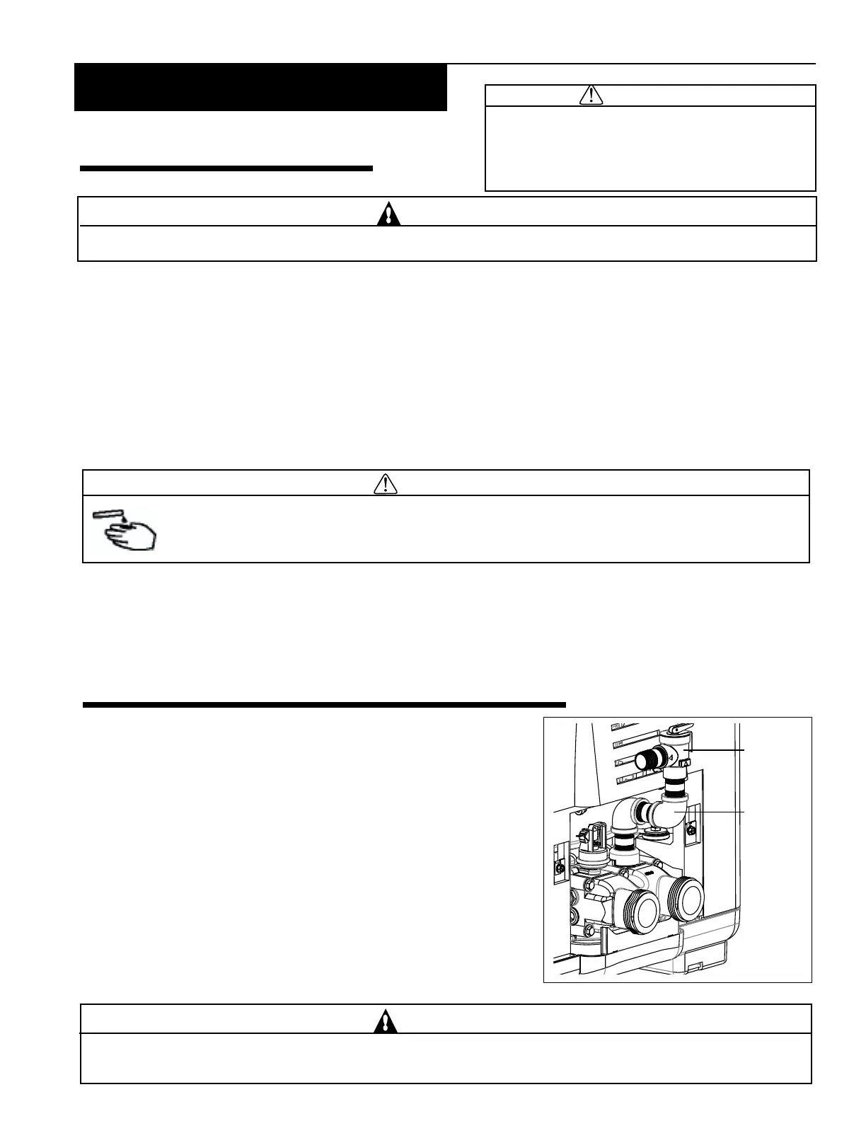
Figure 47.
The relief valve must be installed vertically. To install the valve, use a
19 mm x 5 mm brass nipple at the manifold, the two brass elbows and nipples
are (user supplied), as shown in Figure 47. No valve is allowed to be placed
between the manifold adapter and the relief valve.
To avoid water damage or scalding from operation of the relief valve,
install a drain pipe in the outlet of the pressure relief valve that will direct
water discharging from the valve to a safe place for disposal. Do not install
any reducing couplings or valves in the drain pipe. The drain pipe must be
installed so as to allow complete drainage from the valve and drain line. The
relief valve should be tested at least once a year by lifting the valve lever.
Relief
Valve
(PRV)
Install brass
nipple and
elbow as
shown for a
Pressure
Relief Valve
(PRV)