MASTERTEMP
125 Pool and Spa Heater Installation and User’s Guide 460906 Rev. D 8/2020
10
HEATER DESCRIPTION
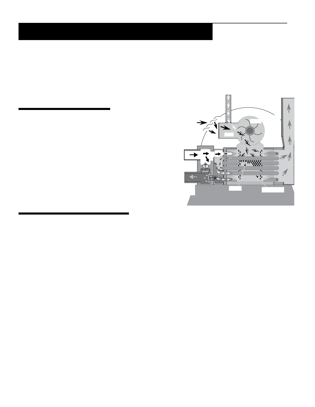
Figure 1 shows a diagram of the heater showing how it operates.
Precisely matched orice plates meter the air and gas into the mixer.
The blower draws the air and gas through the mixer and forces it into
the burner’s ame holder. A sealed heat exchanger surrounds the ame
holder, discharging exhaust gases out the ue.
Two inch PVC water piping connects directly to the manifold/header on
the heat exchanger using 1.5” PVC slip unions provided with the heater.
The outer manifold remains cool; no heat sinks are required. A thermal
regulator and an internal bypass regulate the water ow through the heat
exchanger to maintain the correct outlet temperature. The heater operator
control panel board assembly is located on top of the heater.
SEQUENCE OF OPERATION
An electronic temperature sensing thermistor in the manifold adapter inlet controls the heater operation. When the inlet
water temperature drops below the temperature set on the operatingcontrol, the burnercontroller supplies power to the
combustion airblower through a series of safetyinterlocks. The interlocks consist of;
• the pressureswitch (PS), which senses that the pump is running,
• the highlimitswitch (HLS), which opens if the heat exchanger outlet temperature goes above 55° C (131° F), and
• the airowswitch (AFS), which senses the pressure drop across the air metering orice,
• the automaticgasshut-off (AGS) switch, which opens if the heat exchanger outlet temperature goes above 60° C
(140° F).
• the inlettemperaturecontrolswitch, which opens if the inlet temperature goes above 45° C (110° F).
• the stackuesensor (SFS), which shuts down the heater if the ue gas temperature reaches 249° C (480° F).
The air ow switch (AFS) senses the pressure drop across the air metering orice. As soon as there is sufcient air ow,
the AFS closes, closing the circuit to the hotsurfaceigniter (HSI), which ignites the fuel mixture. On a call for heat, the
blower and HSI are energized. In about 20 seconds, the gas valve opens and ignition occurs. The HSI then switches to a
sensing mode and monitors the ame. The heater is equipped with a digital operating control that enables the user to pre-
set the desired pool and spa water temperatures. The control enables the user to select between pool and spa heating, and
features a digital display that indicates the water temperature.
PUTTING THE HEATER INTO SERVICE
If the heater is installed below the level of the pool, or more than two feet above pool level, the pressure switch setting
should be adjusted. See WATER PRESSURE SWITCH, in the SAFETY CONTROLS Section (page 44).
Before putting the heater into service for the rst time, follow the instructions under “BEFORESTART-UP”(page42) in the front
of this manual. Check for proper operation of the heater by following the steps under “OPERATIONINSTRUCTIONS,”seepage43.
Damagetoequipmentcausedbyimproperinstallationorrepairwillvoidthewarranty.
Section 1. Installation Instructions
Section 1. Installation
Gas
Air
Mixer
Blower
Inlet
(Cold
Water)
Exhaust
Heating Coils
Outlet
(Mixed
Water)
Burner
Figure 1.
This product must be installed and serviced by a professional service technician, qualied in pool heater installation.
Pentair strongly recommends that all vents, pipes and exhaust systems be initially and periodically tested for proper
operation. This testing can be accomplished by using a hand-held carbon monoxide meter and/or by consulting with
a gas professional. Pool heaters must be used in conjunction with carbon monoxide detectors installed near the pool
heater. The carbon monoxide detectors must be periodically inspected for proper operation so as to insure continued
safety. Broken or malfunctioning carbon monoxide detectors must be replaced immediately. If not tted on the heater,
the installer must installed any safety devices according to the current
local codes.