460906 Rev. D 8/2020 MASTERTEMP
125 Pool and Spa Heater Installation and User’s Guide
17
Section 1. Installation Instructions
TESTING GAS LEAKS AND GAS PRESSURE
THE MASTERTEMP HEATER IS INTENDED FOR INSTALLATION WITH A METERED GAS PRESSURE REGULATOR.
Before operating the heater, the heater and its gas connections must be leak tested. DoNOTuseanopenametotest
forleaks. Test all gas connections for leaks with soapy water.
The gas valve must be completely disconnected from the gas supply piping system during any pressure testing of that
system at test pressures in excess of 6.0 kPa.
TESTING THE GAS PRESSURE THROUGH THE COMBINATION GAS CONTROL VALVE
WARNING
Risk of fire and explosion. Alteration, service, or maintenance of the Combination Gas Control Valve can lead to fire or explosion,
causing loss of life, personal injury, and/or property damage. DO NOT ATTEMPT TO ADJUST THE GAS CONTROL VALVE.
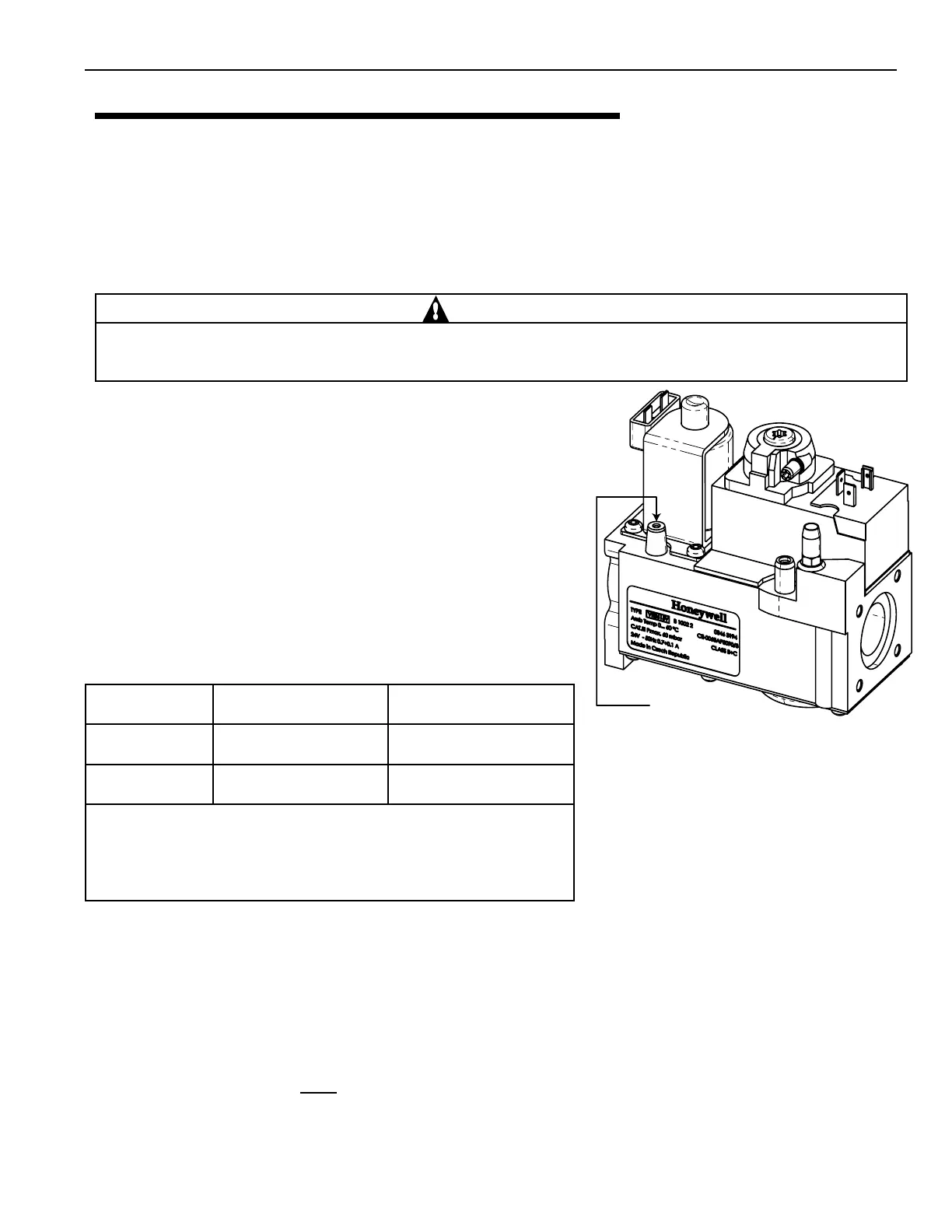
Figure 10.
1. Shut off the gas supply to the heater.
2. Loosen the small screw inside the pressure tap as shown in Figure 10.
3. Connect the manometer hose.
4. Open the gas supply to the heater.
5. Turn on the heater.
6. Take the gas pressure reading.
7. Turn off the heater.
8. Shut off the gas supply to the heater.
9. Disconnect the manometer hose.
10. Tighten the small screw inside the pressure tap.
Description Type Gas Supply Pressure
Natural Gas
1.0 kPa 6.0 Kpa
Propane Gas
2.5 kPa 6.0 pKa
NOTE: The minimum value approved for input adjustment. Do not exceed the
maximum supply pressure.
All readings must be taken while heater is operating. Any adjustments or
readings made while heater is off will result in performance problems.
INLET GAS PRESSURE REQUIREMENTS
CAUTION! This appliance is equipped with an unconventional gas control valve that is factory set with a manifold
pressure of 11 ± 5 kPa. Installation or service must be performed by a qualied installer, service agency, or the gas
supplier. If this control valve is replaced, it must be replaced with an identical control. The combination gas valve
incorporates dual shut-off valves and a negative-pressure regulator. For proper operation, the regulated pressure at the
outlet manifold of the valve must be 11 ± 5 kPa below the reference pressure at the blower mixer inlet, and the gas
valve ‘VENT’ tap must be connected to the end cap air orice as shown in Figure 9 (page 16).DONOTattemptto
adjustthegasinputbyadjustingtheregulatorsetting.Thecorrectgasregulatorsettingisrequiredtomaintain
propercombustionandmustNOTbealtered.
Lightly loosen the
small screw inside the pressure tap,
and attach/connect the manometer hose.
Table 2.