MASTERTEMP
125 Pool and Spa Heater Installation and User’s Guide 460906 Rev. D 8/2020
16
GAS CONNECTIONS
GAS LINE INSTALLATIONS
The gas supply must be installed in accordance with the Gas Installation Code, AS/NZS 5263.1.12:2019
and all applicable local codes. Before installing the gas line, be sure to check which gas the heater has been designed to
burn. This is important because different types of gas require different gas pipe sizes. The rating plate on the heater will
indicate which gas the heater is designed to burn. Table 2 below shows the recommended gas inlet pipe sizes required
for the distance from the gas meter to the heater. The table is for natural gas at a specic gravity of .65 and propane at
a specic gravity of 1.55.
When sizing gas lines, calculate 0.9 additional meters of straight pipe for every elbow used. When installing the gas line,
avoid getting dirt, grease or other foreign material in the pipe as this may cause damage to the gas valve, which may result in
heater failure.
The gas meter should be checked to make sure that it will supply enough gas to the heater and any other appliances that
may be used on the same meter. Insufcient gas supply will cause the heater to operate below its designed performance or
not at all. The gas line from the meter will usually be of a larger size than the gas valve supplied with the heater. Therefore
a reduction of the connecting gas pipe will be necessary. Make this reduction as close to the heater as possible. If the
gas pressure is not adjusted to the correct working pressure, the heater will be over gassed and cause serious damage
within minutes. This damage is not covered under the heater warranty.
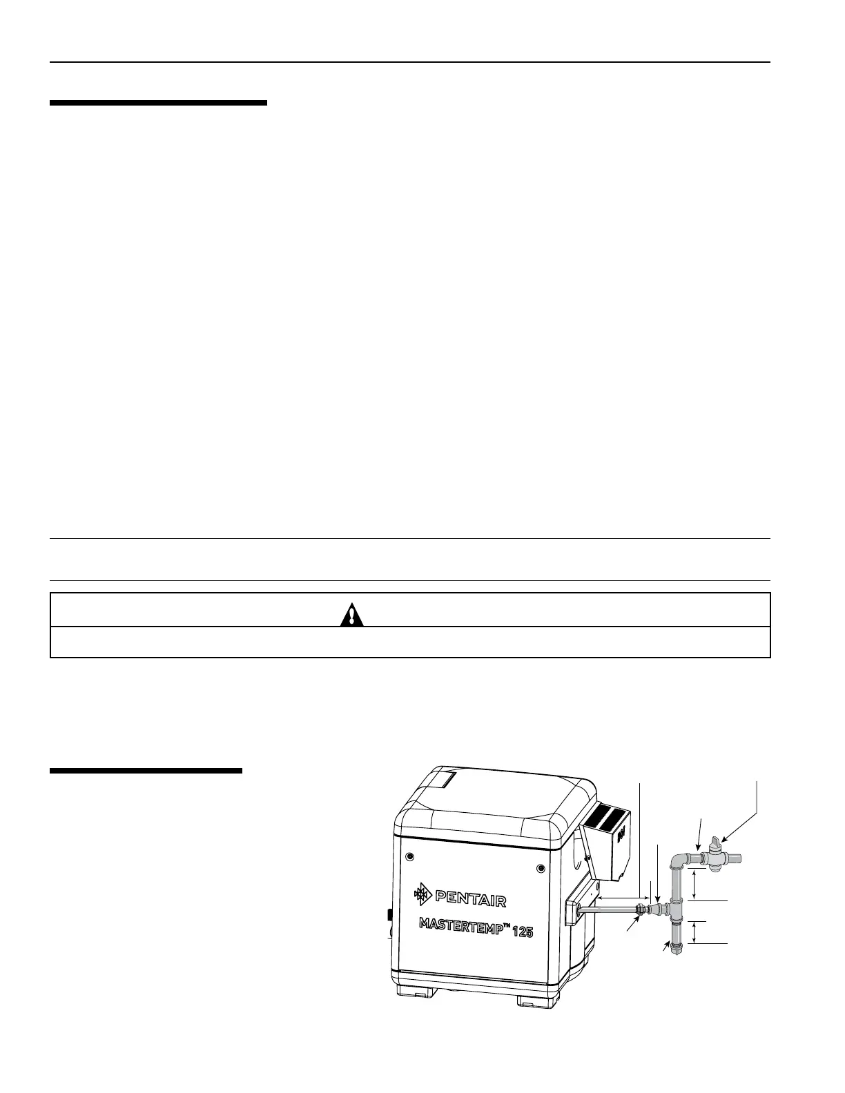
Install a manual shut-off valve that conforms with Type1orType2asperAG201and/orAS4617standards and a
sediment trap/drip leg and union located outside the heater panels, see Figure 9. Do not use a restrictive gas cock.
The heater and any other gas appliances must be disconnected from the gas supply piping system during any pressure
testing on that system, (greater than 6.0 kPa). The heater and its gas connection must be leak tested before placing the
heater in operation. Donotuseametotestthegasline. Use soapy water or another nonammable method.
NOTE
A manual main shut-off valve must be installed externally to the heater.
WARNING
DO NOT INSTALL THE GAS LINE UNION INSIDE THE HEATER CABINET. THIS WILL VOID YOUR WARRANTY.
SEDIMENT TRAPS
Install a sediment trap and union located outside
the heater panels in accordance with National code
requirements. Do not use a restrictive gas cock. The
sediment trap shall be either a tee tting with a capped
nipple in the bottom outlet which can be removed for
cleaning, as shown in Figure 9, or an other device
recognized as an effective sediment trap. All gas
piping should be tested after installation in accordance
with local codes.
Figure 9.
Section 1. Installation Instructions
Manual
Shut-off
Valve
Sediment
Trap
Union
At least 9"
At least 3"
1" Dia. or larger
(See "Recommended
Pipe Sizes" Chart)
Gas line from
Valve
Bell
Reducer