MASTERTEMP
125 Pool and Spa Heater Installation and User’s Guide 460906 Rev. D 8/2020
14
BELOW POOL LEVEL INSTALLATION
If the heater is below water level, the pressure switch must be
adjusted. This adjustment must be done by a qualied service
technician. See following CAUTION before installation.
CAUTION
BELOW OR ABOVE POOL INSTALLATION
The WATER PRESSURE RELIEF VALVE SWITCH is set in the factory at 21 kPa (± 5 kPa) (3 ± 0.7 psi). This setting is for
a heater installed at pool level. If the heater is to be installed more than 0.3 m (1ft.) above or below, the water pressure
switch must be adjusted by a qualified service technician. See page 57.
FLOW SWITCH
If the heater is installed more than 1.5 m (5)’ above the pool or more than 1.2 m (4’) below the pool level, you will be
beyond the limits of the pressure switch and a flow switch must be installed. Locate and install the flow switch externally
on the outlet piping from the heater, as close as possible to the heater. Connect the flow switch wires in place of the
water pressure switch wires.
Section 1. Installation Instructions
VALVES
When any equipment is located below the surface of the pool or spa, valves should be placed in the circulation piping
system to isolate the equipment from the pool or spa. Check valves are recommended to prevent back-siphoning.
Back-siphoning is most likely to occur when the pump stops, creating a pressure-suction differential. Do NOT sanitize the
pool by putting chlorine tablets or sticks into the skimmer(s). When the pump is off, this will cause a high concentration
of chlorine to enter the heater, which could cause corrosion damage to the heat exchanger.
CAUTION
Exercise care when installing chemical feeders so as to not allow back siphoning of chemical into the heater, filters or
pump. When chemical feeders are installed in the circulation of the piping system, make sure the feeder outlet line is
down stream of the heater, and is equipped with a positive seal noncorrosive “Check Valve”, (P/N R172288), between
the feeder and heater.
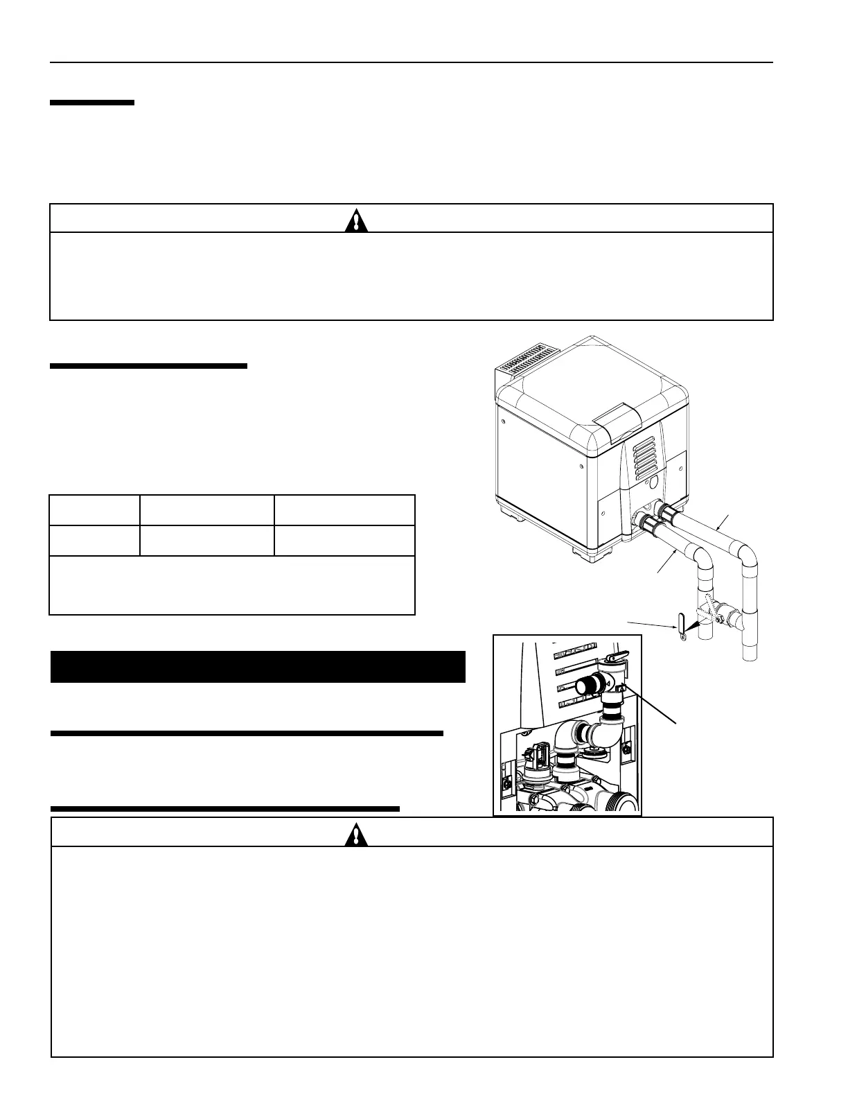
MANUAL BY-PASS
Where the water ow rate exceeds the maximum 70 GPM (265 LPM),
a manual bypass should be installed and adjusted. After installing the
valve, adjust the valve to bring the ow rate within the acceptable range.
Then remove the valve handle or lock it in place to avoid tampering.
See Figure 7.
Table 1.
See page 57 for Pressure Relief Valve (optional)
Cool water in
Warm water out
OUTLET TO POOL
INLET TO HEATER
1. Set Manual By-Pass Valve.
2. Remove Handle.
Figure 7.
Model Min. LPM (GPM) Max. LPM (GPM) *
125 76 (20) 265 (70)
* DO NOT EXCEED THE MAXIMUM RECOMMENDED FLOW RATE
FOR THE CONNECTING PIPING.
PRESSURE
RELIEF
VALVE