VMP2 Configuration
ID 24855, Rev. 02Page 4 - 14 © 2002 PEP Modular Computers GmbH
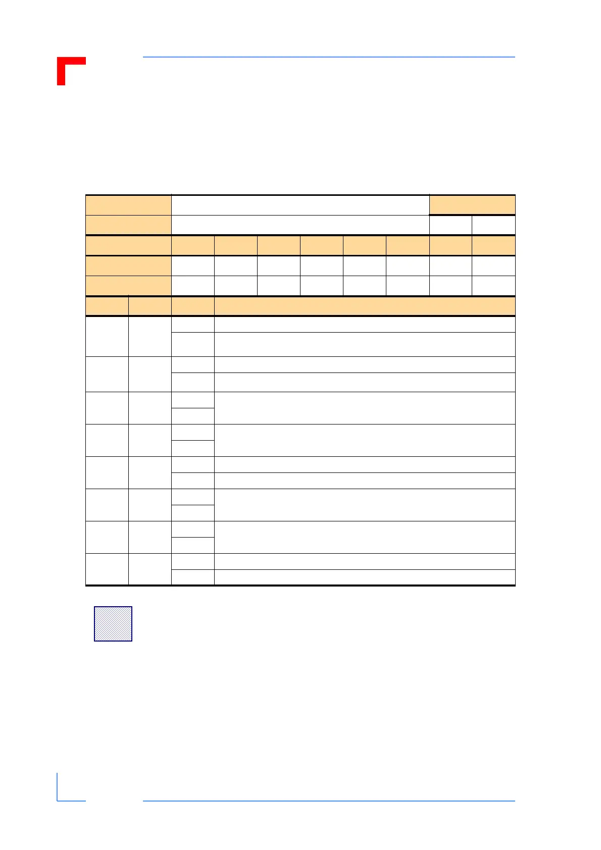
4.3.4.7 Control Register
The Control register provides access to the front panel general purpose LED’s (LED1/
Green and LED2/Red), allows for the generation of a software reset of the system, and
is used to control the configuration of the SER either for RS-232 or RS-485 operation.
Table 4-12: Control Register
REGISTER NAME
CONTROL
ACCESS
ADDRESS
0xFFE0 001A R W
BIT POSITION
MSB
7 6 5 4 3 2 1 0
LSB
CONTENT
RS_CTL Res. Res. S_RST Res. Res. GPLED2 GPLED1
DEFAULT
n/a n/a 0 n/a 0 0 0 0
BIT NAME VAL DESCRIPTION
0
Indicator
LED1/
Green
0 GPLED1 LED1G (green) off
1
GPLED1 LED1G (green) on
1
Indicator
LED2/Red
0 GPLED2 (optional, red) off
1
GPLED2 (optional, red) on
2Res.
0
Reserved
1
3Res.
0
Reserved
1
4S_RST
0 No operation
1 Causes a software reset (S_RST) to be initiated
5Res.
0
Reserved
1
6Res.
0
Reserved
1
7RS_CTL
0
SER connector configured to act as an RS232 interface (default)
1
SER connector configured to act as an RS485 interface
!
Warning:
When setting bit 7 the user must ensure that the corresponding
interface is also an RS485. A mismatch will risk damage to the
VMP2 and/or the application.