Do you have a question about the PEP Modular Computers VMP2 and is the answer not in the manual?
Warns about electrical shock hazards and necessary precautions.
Details precautions for handling ESD-sensitive devices and unpacking procedures.
Overview of the VMP2 as a comprehensive computing platform for VME applications.
Details the VMP2 as a VME PowerPC-based single-board computer for industrial environments.
Describes the VMP2's architecture, VMEbus, Ethernet, and serial interfaces.
Lists key hardware specifications including CPU, memory, interfaces, and physical dimensions.
Details compliance with CE, mechanical, and environmental standards.
Lists relevant standards and publications for VME systems and PMC modules.
Illustrates the VMP2's internal components and their interconnections.
Shows front panel layouts and LED key for standard and optoisolated versions.
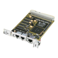
Displays front and reverse views of the VMP2 board, highlighting key components.
Details the VMP2's main features, including CPU, memory, interfaces, and special functions.
Details VME, Ethernet, Serial, PCI, Debug, and Temperature Sensor interfaces.
Explains features like Watchdog Timer, RTC, Reset/Abort, and Front Panel LEDs.
Provides steps for installing the VMP2 board, including slot selection and serial interface setup.
Details jumper settings for bootstrap loader, socket selection, and RS485 termination.
Provides pin assignments for memory expansion sockets and serial interface expansion connectors.
Illustrates the VMP2's address mapping for VME and onboard devices.
Explains NetBootLoader startup, control transfer, and operator interaction.
Describes ways to interface with NetBootLoader: ABT switch, TERM, SER0, and Ethernet.
Outlines functions for NetBootLoader control, system status monitoring, and ftp server access.
Covers initial setup, accessing NetBootLoader, and configuration via commands.
Lists and explains NetBootLoader commands for operation, status, and configuration.
Introduces VMP1-IO1 module as a gateway to PMC modules for VMP2 expansion.
Details PCI Expansion Connector and PMC Interface on the VMP1-IO1 module.
Shows VMP1-IO1 board layout, highlighting connectors for PMC modules.
Illustrates VMP1-IO1 front panel with a window for PMC module bezels.
Lists technical specs for VMP1-IO1 module, including PCI standards, temperature, and dimensions.
Provides step-by-step instructions for installing VMP1-IO1 module and PMC modules.
Details pin assignments for Jn1 (CON4) and Jn2 (CON5) PCI connectors.
Explains jumper settings for IO1 module based on its position relative to other modules.
Details the VMP1-Post tool for hardware and software debugging purposes.
Details the optoisolated RS485 transition module for VMP2 systems.
Explains the JTAG subsystem, device access, and JTAG chain configuration.
Details the CP320-TR1 module for optoisolated RS485 serial interface.
Details the CP320-TR2 module for optoisolated RS232 serial interface.
Details the PMC-HDD1 module for adding mass storage capacity via IDE drives.
| Brand | PEP Modular Computers |
|---|---|
| Model | VMP2 |
| Category | Computer Hardware |
| Language | English |