2023-11
80
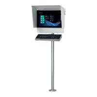
VisuNet FLX System
Interfaces
6Interfaces
6.1 Computing Unit - Interface connectors
For detailed information on the interfaces of the computing units refer to the BPC3200-* manual
or DMU3200-* manual.
6.1.1 Power Limitations
Maximum output currents VisuNet FLX system installation
Refer to the VisuNet FLX Panel Mount manual and BPC3200-* manual to get detailed informa-
tion on the maximum output current of these installations.
Caution!
Damage to the electronics!
The electronics can be damaged if plug-in connections are connected or disconnected while
power is still being applied.
Make sure that no power is being applied while connecting and disconnecting cables!
Warning!
Interfaces must have a strain relief in Ex-operation.
This can be achieved with the ATEN Locks (#548400)
Caution!
Our units are power-limited for compliance with Ex requirements and protection against over-
heating. For this purpose, the maximum operating conditions (maximum operating temperature
at maximum load) are considered.
It is absolutely necessary to consider maximum allowed output currents when installing the Vis-
uNet FLX in Zone 2/22 environment.
Port System
USB 2.0 250 mA
USB Ex-i Port A 100 mA
USB Ex-i Port B 100 mA
USB 3.0 Port A 500 mA
USB 3.0 Port B -
Serial Ports (shared) 200 mA
Note
For Non-Ex applications, these parameters serve as guide values and allow an increase of the
VisuNet FLX system service life.