44 . DSC 6000 Installation and Hardware Guide
8. Connect the other end of the hose to the COOLING LIQUID OUT connector on the
analyzer. Place a hose clamp around the hose and the metal tube to secure the hose in
place.
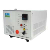
Setting Up The Chiller
1. Fill the reservoir with coolant.
Ensure that the cooling coils are completely covered. The maximum coolant level is
25 mm below the top of the reservoir.
2. Switch the chiller on at the mains supply and at the switch on the rear of the control
unit (NOT using the Power switch on the front of the control unit).
3. When switching on the chiller for the first time, select the display language by rotating
the Select/Set control on the front panel, and then pressing to select the desired option.
The chiller controller will continue with its start-up sequence and then display “Standby”
when ready.
4. Set the safety set temperature on the controller using a flat screwdriver to rotate the
control to the maximum temperature to which the bath should be heated.
5. Press the Power switch on the front panel.
The pump will begin operating.
6. Top up the coolant reservoir to compensate for the fluid in the external circuit.
7. Rotate the Select/Set control on the front panel until the Pump/AutoTune menu is
displayed.
8. Press the Select/Set control until the pump speed bar is highlighted.
9. Rotate the Select/Set control to adjust the pump speed, and press the control to accept
the new setting.
CAUTION
ATTENTION
The heat exchanger of the DSC 6000 will NOT accept pressure. Use the
lowest flow rate that provides sufficient cooling for your experiment to
minimize the pressure in the system.
L'échangeur de chaleur du DSC 6000 n'acceptera PAS la pression.
Utilisez le débit le plus bas qui procure un refroidissement suffisant pour
votre expérience afin de minimiser la pression dans le système.
CAUTION
ATTENTION
It is essential to maintain a very constant flow rate of coolant. The liquid
should be free of air bubbles. Changes in the liquid flow rate or the
presence of air bubbles will reduce the quality of the measurement
signal.
Il est essentiel de maintenir un débit constant de liquide de
refroidissement. Le liquide doit être exempt de bulles d'a
ir. Des
changements dans le débit de liquide ou la présence de bulles d'air
réduiront la qualité du signal de mesure.
 Loading...
