128 KENR9126
Troubleshooting Section
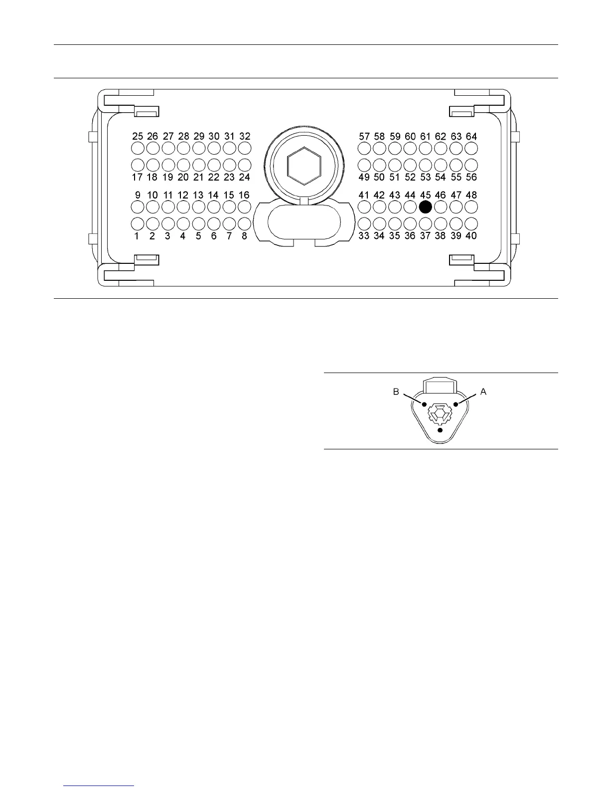
g02192045
Illustration 31
P1 terminals that are as sociated with the coolant level sensor
(P1-45) Coolant level
C. Perform a 45 N (10 lb) pull test on each of the
wires that are associated with the circuit for the
coolant level sensor.
D. Check the allen head screw on each ECM
connector for the proper torque. Refer to the
diagnostic functional test Troubleshooting,
“Electrical Connectors - Inspect”.
Expected Result:
All connectors, pins, and sockets are completely
coupled and/or inserted, and the harness and wiring
are free of corrosion, of abrasion or of pinch points.
Results:
•
OK – The connectors and wiring are OK. Proceed
to Test Step 2.
•
Not OK – There is a problem with the connectors
and/or the wiring.
Repair: Repair the wiring and connectors or
replace the wiring or the connectors. Ensure that
all of the seals are properly connected. Verify that
the repair eliminates the problem.
Verify that the repair eliminates the problem.
STOP.
Test Step 2. Check the Supply Voltage at
the Sensor Connector
A. Disconnect the coolant level sensor.
B. Restore the electrical power to the ECM.
g01132478
Illustration 32
Harness connector for the coolant level sensor
(A) Battery positive
(B) Battery negative
C. Measure the voltage between terminals A and B at
the harness connector for the coolant level sensor.
D. Remove the electrical power from th e ECM.
Expected Result:
The voltage measurement is 12 or 24 VDC.
Results:
•
OK – The voltage measurement is 12 or 24 VDC.
The supply voltage is reaching the sensor. Proceed
to Test Step 3.
•
Not OK – The voltage measurement is not 12 or
24 VDC. The digital sensor supply voltage is not
reaching the sensor.