156 KENR9126
Troubleshooting Section
g01803516
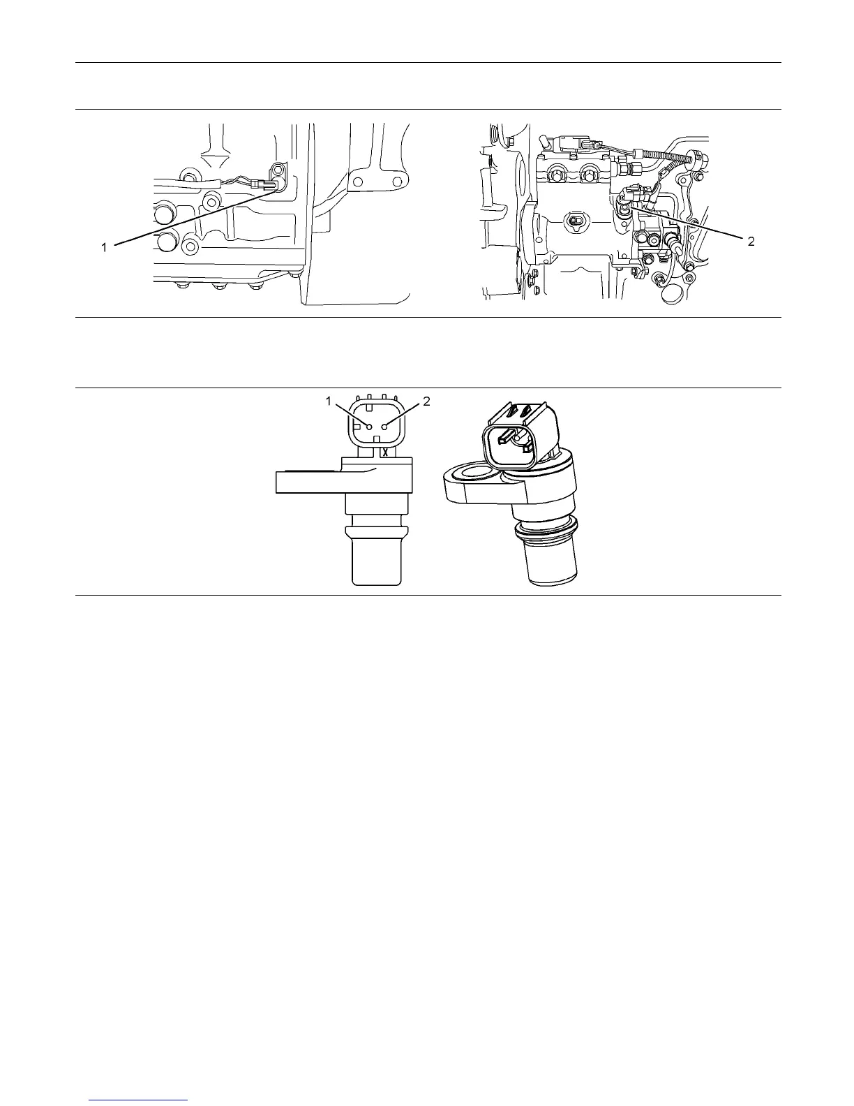
Illustration 57
Detailed view of the sensor locations on the engine
(1) Primary spee d/timing sensor (2) Secondary speed/timing sensor
g01212995
Illustration 58
Typical example of the speed/timing sensors
(1) Voltage Supply (+8 Volts DC) (2) Signal (S ig)
Test Step 1. Inspect the Electrical
Connectors and the Harness
A. Turn the keyswitch to the OFF position.
B. Thoroughly inspect the P2 connector and
the suspect sensor connections. Refer to
Troubleshooting, “Electrical Connectors - Inspect”.
C. Perform a 45 N (10 lb) pull test on each of
the wires in the suspect sensor connector and
the sensor connections at the ECM. The wire
connectors are shown in illustration 56.
D. Check that the ground connection on the ECM and
the negative terminal on the battery are correctly
installed.
E. Check the ground connection on the ECM for
abrasions and pinch points.
F. Check the screw for the ECM connector for the
correcttorqueof5.0N·m(44lbin).
G. Check the harness for abrasion and pinch points
from the suspect sensor to the ECM.
H. Check that the suspect sensor is installed
correctly. Check that the suspect sensor is fully
seated into the engine. Check that the connector
on the sensor is securely latched.
Expected Result:
The electrical connectors and the cables are correctly
installed.
Results:
•
OK – The harness is OK. Proceed to Test Step 2.
•
Not OK
Repair: Repair the faulty connectors or the
harness and/or replace the faulty connectors or the
harness. Ensure that all of the seals are correctly in
place and ensure that the connectors are correctly
coupled.
If a sensor must be replaced or the sensor must be
reinstalled, complete all of the following tasks: