206 KENR9126
Troubleshooting Section
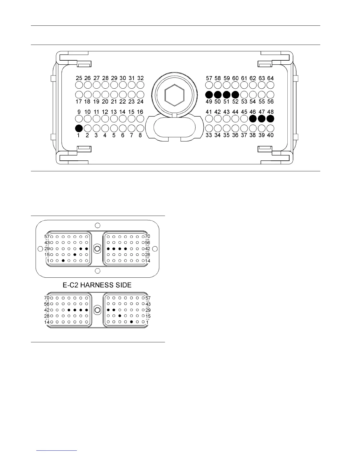
g02191993
Illustration 88
P1 terminals for the various switches
(P1-1) “Neg ative Battery”
(P1-52) “Remote s hutdown sw itch”
(P1-51) “Maintenance c lear s witch”
(P1-50) “Trip c lear switch”
(P1-49) “Trolling m ode switch”
(P1-48) “ Slow v essel mode sw itch”
(P1-47) “Synchronize switch 1”
(P1-46) “Synchronize switch 2”
g02247954
Illustration 89
E-C2 terminals that are associated with the switch inputs
(3) −Battery
(19) “Trip clear s witch”
(36) “Remote shutdown s witch”
(37) “Trolling mode s witch”
(38) “Slow vessel mode switch”
(39) “Maintenance c lear switch”
(34) “Synchr on ize switch 1 ”
(35) “Synchr on ize switch 2 ”
C. Perform a 45 N (10 lb) pull test on each of the
wires in the circuit for the suspect switch.
D. Check the allen head screw on the connector
for the Electronic Control Module (ECM) for the
proper torque. Refer to the diagnostic functional
test Troubleshooting, “Electrical Connectors -
Inspect” for the correct torque values.
E. Check the allen head screw on the customer
connector for the proper torque. Refer to the
diagnostic functional test Troubleshooting,
“Electrical Connectors - Inspect”.
F. Check the harness and wiring for abrasions and
for pinch points from the battery to the ECM.
Expected Result:
All connectors, pins, and sockets are completely
coupled and/or inserted, and the harness and wiring
are free of corrosion, of abrasion or of pinch points.
Results:
•
OK – The wiring and connectors are OK. Proceed
to Test Step 2.
•
Not OK – There is a problem with the wiring and/or
a connector.
Repair: Repair the wiring and/or the connector.
Replace parts, if necessary. Ensure that all of the
seals are properly connected. Verify that the repair
eliminates the problem.
STOP.