13
Installing your IOLAN+
IOLAN+ Installation 2
Below is a step-by-step guide on how to configure IOLAN+.
You can also reference the
IOLAN+ Quick Start Guide
.
First connect IOLAN+ to a network then begin configuring
the unit for your application. Additional information on
configuring modems and printers follows.
2.1 Connecting
to your
Network
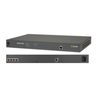
IOLAN+ and IOLAN+ connect to your Ethernet
network via one of the three auto sensing ports: 10BASE-T
(twisted pair), 10BASE2 (thin) or AUI. IOLAN+ 102/104 has
10BASE-T only. For IOLAN+ and IOLAN+
, the default
is 10BASE2.
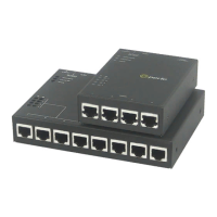
10BASE-T
(twisted pair)
Attach the RJ connector from a hub directly to IOLAN+
twisted pair port.
10BASE2
(Thin Ethernet)
Attach a BNC T connector directly to IOLAN+. If your
IOLAN+ is the termination point for the cable you need to
add a terminator. Always ensure that each segment of the
thin Ethernet cable is at least 0.5m in length. The maximum
length for a thin Ethernet cable is 185 metres.
AUI port
The AUI connector allows an external transceiver to be
connected. This allows a number of different interfaces to
connect including 10BASE5 (or thick) and fibre optic transceivers.
2.2 Switching on
IOLAN+
The IOLAN+ power supply accepts input voltages in the
range 110 to 240V AC, allowing it to be used world-wide.
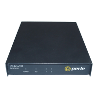
The IOLAN+ 102/104 has an external power supply unit.
After you connect your LAN interface, you can power up the
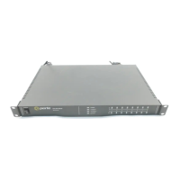
unit. The green power indicator at the side (or front for rack
and 102/104 units) should be lit. If the unit fails to power up
with the green power indicator lit, disconnect the unit and
contact your dealer for help.