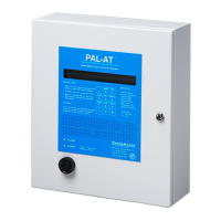
PAL-AT Installation Manual
19
3.3 Panel Wiring
The standard Zener Barrier Panel (ZBP) includes one zener barrier assembly (ZBA) and has provisions to
install three additional ZBA’s. Each ZBA has a 2” [50 mm] coaxial cable lead, a 5’ [1.5 m] coaxial lead and
a 2” [50 mm] ground wire.
The 5’ [2 m] cable should be routed through conduit and connected to the appropriate cable plug in the
PAL-AT panel. The jumper cable to the PAL-AT sensing string should be connected to the fuse holder
and adjacent terminal blocks for the appropriate cable number. The jumper cable should have a ferrule
on the center conductor and two ferrules on the braid. Refer to section 8, Cable Connectors, for details.
A customer supplied earth ground wire, minimum 12 AWG [4 mm
2
], must be connected between
the ground connection on the upper right corner of the white back plate of the enclosure and the
ground bus of the power distribution panel.
3.4 Zener Barrier Assembly (ZBA) Installation
Refer to figure 3-3 to install a ZBA.
1. If an existing ZBA is to be replaced, loosen the four screws on the terminal strip for the ground wire,
coaxial cable center conductor, and two coaxial cable braid wire ferrules. Lift the ZBA out of the mounting
clip. Remove the end of the 5 ft. long cable from the connector in the PAL-AT panel.
2. Position and rotate the new ZBA so the 2” ground wire aligns with the appropriate ground terminal
(green/yellow terminal). Note the ground terminal for barrier #4 is on the opposite side of the fuse holder
as the other barriers. Loosely insert the ground wire, the coaxial center conductor ferrule and two braid
wire ferrules into the ground terminal, fuse holder and adjacent terminals. The ground wire ferrule is a
snug fit in the terminal and may have to be rotated slightly to insert fully.
3. Press and hold the ground wire fully inserted into the ground terminal, while tightening the terminal screw.
Next, press and hold in place the coaxial center conductor ferrule into the fuse terminal and tighten the
terminal screw. Similarly, press, hold and tighten each of the braid wire ferrules. Snap the zener barrier
assembly into the plastic holder. The 5’ [1.5 m] cable should be routed through conduit and connected
to the appropriate cable plug in the PAL-AT panel.
3.5 Fuse Protection
Each Zener Barrier Assembly is protected from external voltage surges by a replaceable fuse in the
terminal strip fuse holder. The 5 x 20 mm fuse is rated 250 mA, 250 V, fast-acting (Littelfuse 0217.250 or
equal). A replacement may be purchased from PermAlert (part # 8067989) or obtained locally.
3.6 Allowable Cables and Probes
Refer to Appendix A – Special Instructions for the PAL-AT control drawing and additional intrinsic safety
requirements for hazardous areas. The following cables, probes, and probe integrators supplied by
PermAlert comply with the allowable electrical characteristics:
Part No. Cable Type Part Number Probe Type Part Number Probe Type
8017705 AGW-Gold 8027888 PHLR-S 8027920 PSTV-L
8017700 AGT-Gold 8027889 PHLR-L 8027633 PTHL-S
8017640 TFH-Gold 8027911 PHLR-P-S 8027970 PTHL-L
8017635 TFH 8027912 PHLR-P-L 8027629 PT10-SC
8017715 JMP-U 8027623 PFS-S 8027932 PT10-SO
8017718 JMP-UD 8027910 PFS-L 8027930 PT10-LC
8017685 JPP 8027624 PSTV-S 8027934 PT10-LO
Note: A PWS probe or a probe integrator connected to a customer supplied probe having an
exposed conductive surface, may not be connected to a ZBA.

 Loading...