PAL-AT Installation Manual
23
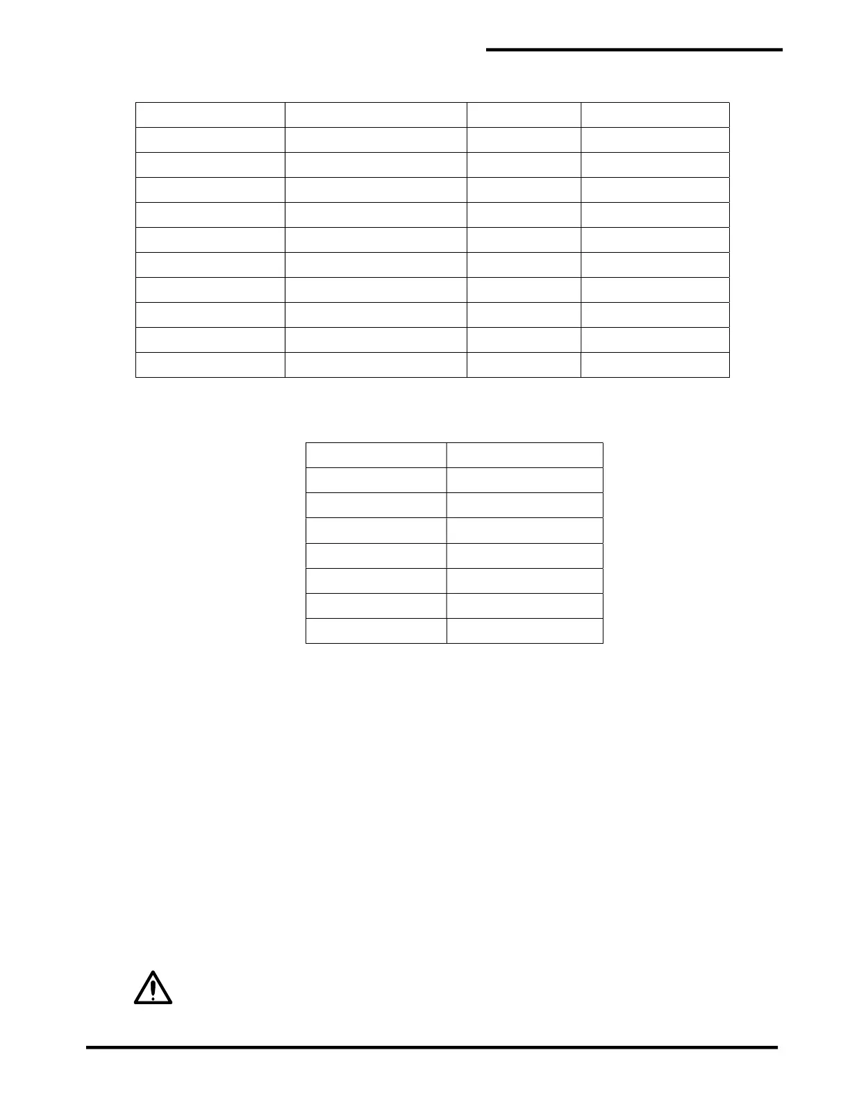
Polypropylene / Polyethylene Piping SDR Sizes
1.5 [40] 4 [100] OK OK
2 [50] 6 [150] OK OK
3 [80] 6 [150] OK OK
4 [100] 8 [200] OK OK
6 [150] 10 [250] OK OK
8 [200] 12 [300] OK OK
10 [250] 14 [350] NO OK
12 [300] 16 [400] N/A OK
14 [350] 18 [450] N/A OK
16 [400] 20 [500] N/A OK
Leak Detection Sizing Chart
For Standard Weight Steel and Fiberglass Pipe
(w/o insulation, 10 gauge steel or fiberglass containment)
Pipe Size (in) [mm]
Casing Size (in) [mm]
2 [50] 6 [150]
3 [80] 6 [150]
4 [100] 8 [200]
6 [150] 10 [250]
8 [200] 12 [300]
10 [250] 14 [350]
12 [300] 16 [400]
Note:
1. Not all pipe types or sizes are shown in the above charts. For different systems,
contact PermAlert.
2. Chart is based on smooth pulling surfaces and installation of guide tubes.
3. Multi pipe system will require factory sizing.
5.2 Pull Points
1. Sensor cable must be “pulled” into the monitored areas using a continuous pull rope free of splices
between pull points. Surfaces the cable contacts during “pulling” operations must be smooth to prevent
snagging or damaging the cable.
2. Generally, pull points can be located at 500' [150 m] intervals for straight runs. Each 90° fitting on the
run reduces the interval by 150' [50 m]. For example, a run of 50' [15 m] with three elbows is allowable
(500' - (3 x 150') = 50').
3. Pull point designs should be selected not only based on accessibility during installation, but potential
future cable replacement. When future cable replacement is a consideration, it is recommended
underground installations have watertight junction boxes or secondary contained access points
installed at grade or in vaults (see figure 5-1).
Caution: Pulling points often become calibration locations. When this occurs, accessibility
to the cable connectors is necessary during the initial commissioning of the PAL-AT and
the system’s setup procedures.