PAL-AT Installation Manual
43
9. Cable mounts (CMA) ordered from PermAlert are adhesive backed. When installations require
mounting to unsealed concrete surfaces, it is recommended construction mastic be used. Care must
be taken to ensure the mastic does not touch the sensor cable. This material can be purchased from
most supply houses. Inspect subfloor (or ceiling) surfaces to be sure it is clean and dry before
beginning installation. Cable tags (CTA) are typically installed on 50' [15 m] intervals for location
purposes.
10. In high traffic areas, cable shields should be used to protect the cable from damage.
11. Service loops (slack cable) should be positioned at connector locations.
12. If the cable is going to be installed in a location that will have limited or challenging access, it is
recommended test ports be installed in a serviceable location for calibration and functional testing.
See section 7.4 for further details.
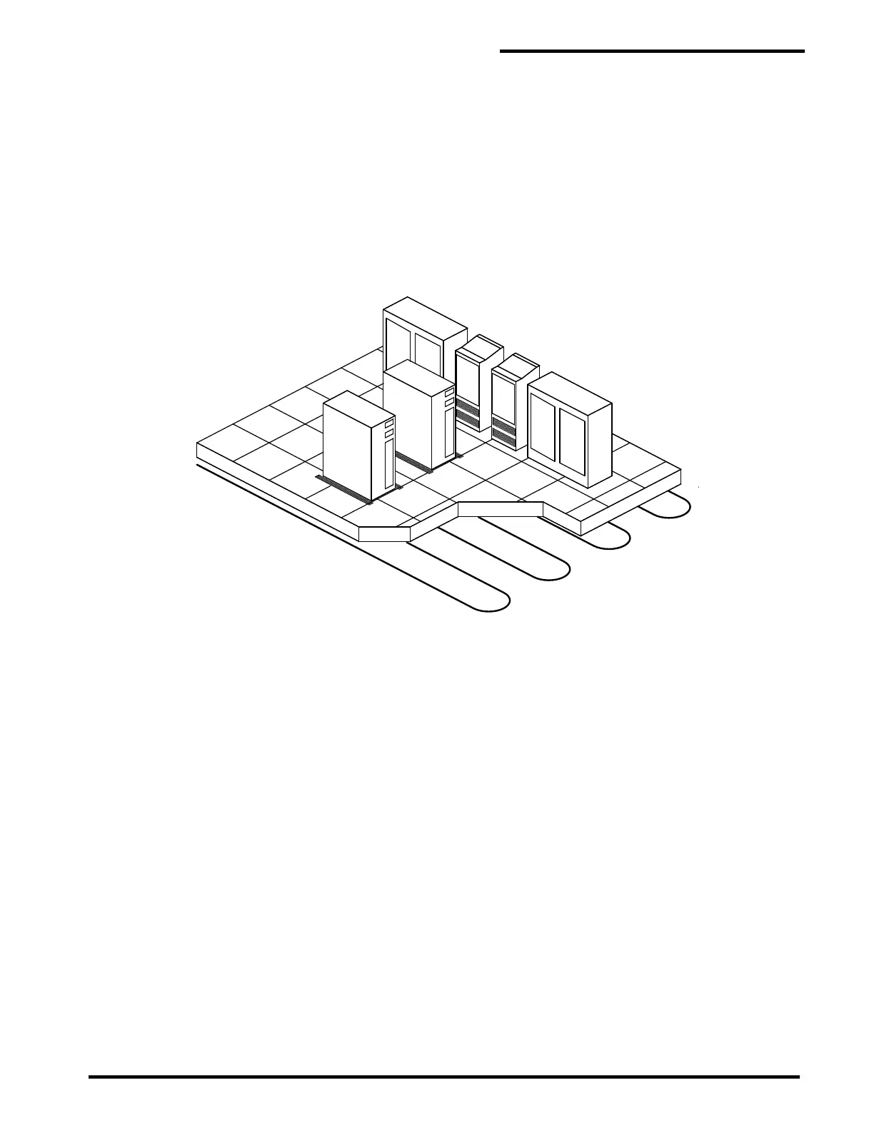
Figure 7-1
Computer Room Floor
7.3 Locator Chart
A graphic display map drawn to scale shall be prepared by the contractor (installer) after completion of
installation from "as built" drawings. The map shall indicate, in relation to the raised floor grid, the location
of the cable, connectors, and landmarks (such as equipment, walls, and drains). Cable distance readings
shall be marked off in 100' [30 m] (or other suitable) increments, beginning at the monitoring panel, to
facilitate physically locating a leak detected by the system. The locator chart should be placed in a plastic
frame suitable for permanent mounting adjacent to the PAL-AT panel.
7.4 Calibration and end of run Access Points
In the event the cable will be inaccessible or in a location where access will be limited or challenging, it is
recommended that calibration points be added. Calibration points shoud be brought to an easily
serviceable location every 500 feet or at the end of serpentine runs along a wall where the cable returns
in the opposite direction. To create a calibration point, jumper cable is run to an accessible junction box to
a 10’ length of sensor before returning to jumper cable back to the main cable run. The 10’ sensor cable
can be used as a calibration and testing point to validate cable lengths and functionality when the main
cable cannot be accessed. At minimum, it is recommended that the end of the cable run be installed in an
accessable location to give a validation point for cable length.