PAL-AT Installation Manual
73
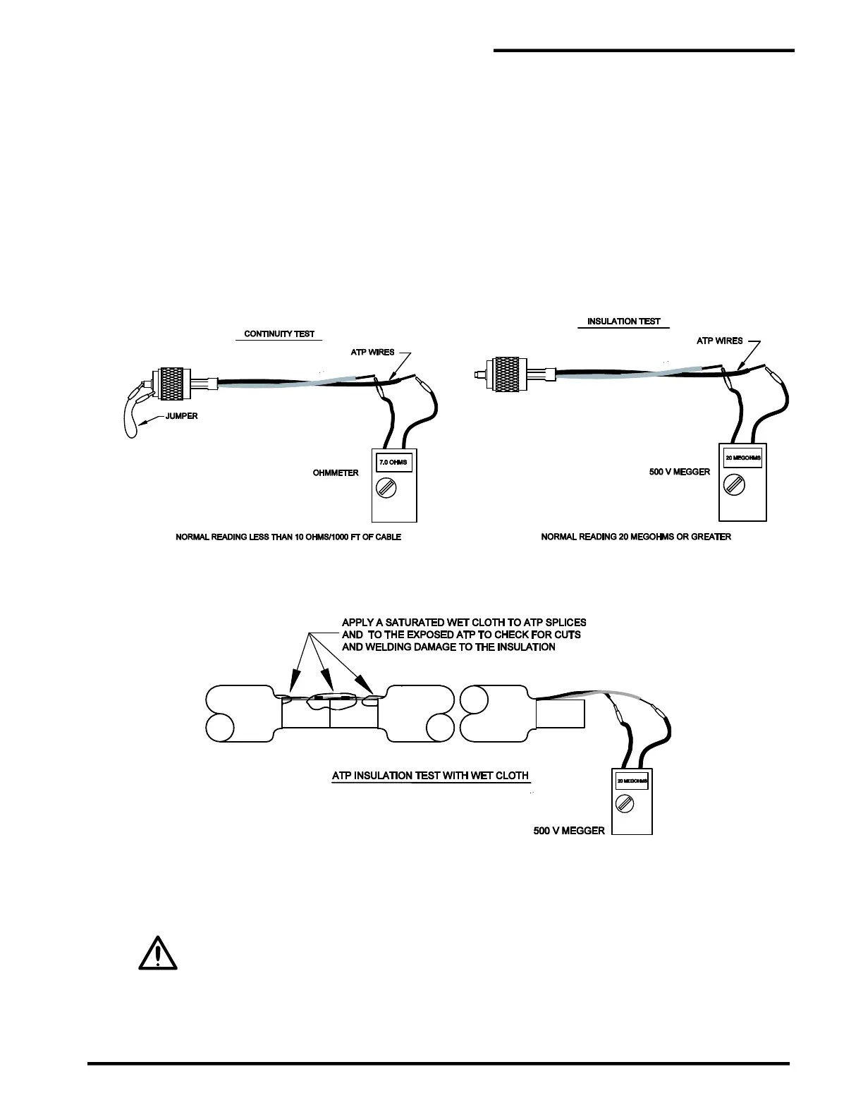
10.5.1 Continuity Test
The continuity test checks for broken cable, open connectors and poor connections. The test can be
performed on the entire ATP sensor string or a partial section.
1. At the start of the pipe (or at the connector in the panel) temporarily connect the red and white wires
together. A short jumper wire with alligator clips or wire nut can be used. If a UHF connector is
installed, connect the jumper between the UHF connector’s center contact and the body of the
connector, as shown. Note: Do not clip onto the threaded coupling ring because it is not tightly
secured and will give intermittent readings
2. Connect the ohmmeter's test leads to the red and white wires on the other end of the cable.
3. The ohmmeter reading should be less than 6 ohms/1000 ft [20 ohms/1000 m] of cable. If it is not,
check the jumper wire, test lead connections and repeat the test. If the problem still persists, check
the last connector installed and correct the problem.
ATP Cable Test Procedures
ATP Wet Cloth Test Procedure
10.5.2 Insulation Test
This insulation test checks for a short between the red and white wires or from either wire to the pipe. The
test can be performed on the entire ATP sensor string or a partial section.
The ATP cable must be disconnected from the PAL-AT panel when conducting the
insulation tests or damage to the equipment will result. A 500-volt megger is used to
measure the resistance between the wires and the carrier pipe.
1. If the jumper wire used in the continuity test is still installed, remove it.
2. Perform this test at the unconnected end of the length of ATP.